Installing the Peripheral Bay Backplane
See Figure 37.
1.Remove the board from its protective wrapper.
2.Position and align the board over the two alignment pins.
3.Attach the eight screws removed earlier.
4.Connect the diskette and
5.Install the peripheral bay in the chassis (see “Installing the Peripheral Bay” on page 118).
6.Install SCSI drives (see
ABCD E
HG F
OM07503
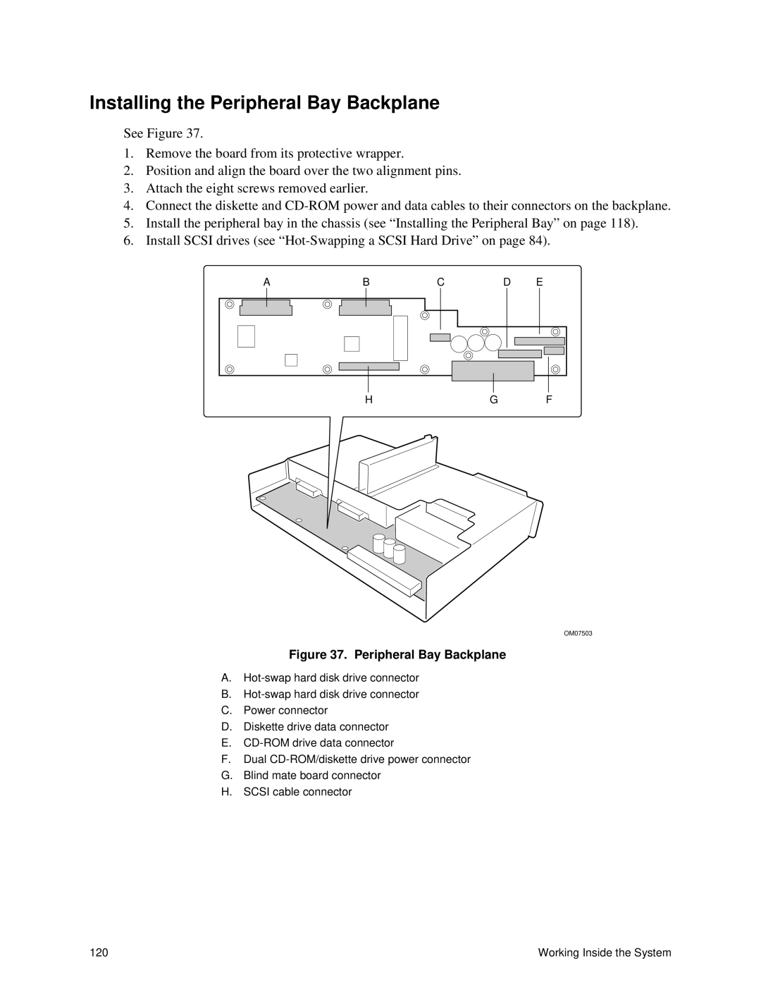
Figure 37. Peripheral Bay Backplane
A.
B.
C.Power connector
D.Diskette drive data connector
E.
F.Dual
G.Blind mate board connector
H.SCSI cable connector
120 | Working Inside the System |