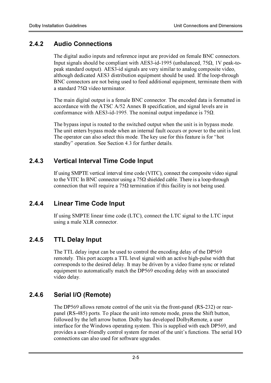
S01/13621 specifications
Dolby Laboratories, a leader in audio and visual technologies, has been at the forefront of sound innovation for decades. One of their notable patents is S01/13621, which encompasses a range of features and advancements designed to enhance audio experiences across various platforms. This patent marks a significant stride in audio encoding and decoding processes, contributing to various applications from cinema to home entertainment systems.The primary feature of S01/13621 revolves around advanced audio compression technologies. These technologies are designed to deliver high-quality sound while minimizing data bandwidth requirements. The result is a more efficient transmission of audio signals, allowing for improved sound fidelity even in constrained environments. This feature is particularly beneficial for streaming services, where maintaining quality while using limited bandwidth is essential.
Another characteristic of the S01/13621 patent is its emphasis on spatial audio. By utilizing techniques such as object-based audio, Dolby enables sound designers and engineers to place audio elements in a three-dimensional sound space. This capability leads to a more immersive audio experience for the listener, making it feel as though they are part of the action, whether in a movie theater or at home.
Dolby’s innovative noise reduction and enhancement algorithms are also part of the S01/13621 technology suite. These algorithms intelligently analyze audio signals to remove unwanted noise while preserving the integrity of the original sound. This feature is crucial in environments where audio quality can be compromised, such as during live recordings or in lower-quality transmission systems.
Furthermore, S01/13621 includes compatibility with various audio formats and systems, ensuring that its advancements are accessible across a wide range of devices. From high-end home theater systems to portable media players, the technology caters to diverse hardware setups, allowing for a seamless audio experience regardless of the platform.
Overall, Dolby Laboratories' S01/13621 represents a robust blend of innovative audio technologies aimed at improving sound quality and user experience. Its features cater to the evolving demands of both content creators and consumers, solidifying Dolby's position as a pioneer in the audiovisual industry and continuously pushing the boundaries of audio excellence.
