ELECTRICAL TROUBLESHOOTING
A volt/ohmmeter (VOM) and the Magnum Opus Wiring schematic (page 12) may be required for this section.
Caution: Portions of this section will require that power be applied to the toilet. Keep hands away from the flush ball, motor drive arm and rotor shaft to prevent personal injury during testing and troubleshooting.
The Magnum Opus control module uses a microprocessor to provide all the automatic and timing functions. The control module is on the right side under the access cover on the top of the toilet. The control module has input and output status lights that can be used in troubleshooting the toilet. The program inside the microprocessor is used for both gravity discharge and
The program in the microprocessor monitors the input and output signals during a normal flush cycle. If the inputs or outputs do not follow the commands of the program, then the microprocessor may go into a "standby" mode and flash an "error" code. The microprocessor is reset by placing the Mode switch in the "Service" position temporarily, then returning the switch to the "Normal" position.
Status Light |
| Color | Function | ||
1 | Low Level |
| Green | Water Level Switch in "Low" position. | |
2 | High Level |
| Green | Water Level Switch in "High" position. | |
3 | Valve Closed |
| Green | Flush valve Closed Limit Switch engaged. | |
4 | Valve Open |
| Green | Flush valve Open Limit Switch engaged. | |
5 | Service Mode |
| Green | Mode Switch in "Service" position. | |
6 | Flush |
| Green | Flush Handle in "Flush" position. | |
7 | Add Water |
| Green | Flush Handle in "Add Water" position. | |
8 | High Vac Switch | Green | Always on (vacuum toilet only). | ||
9 | Holding Tank Full | Green | Always off (vacuum toilet only). | ||
10 | OK to Flush |
| Green | On when not in flush cycle. | |
11 | Do Not Flush |
| Green | On during flush cycle. Also provides error codes. | |
12 | Water Valve |
| Green | Electric water valve energized. | |
13 | +5V |
| Green | Input power | |
ERROR CODES |
|
|
|
| |
Status Light | No. of Flashes | Pause | Condition | ||
10 | OK to Flush |
| 1 | .5 sec. | Mode Switch in SERVICE position |
11 | Do Not Flush |
| 1 | 2 sec. | VALVE OPEN Limit Switch problem |
11 | Do Not Flush |
| 2 | 2 sec. | VALVE CLOSED Limit Switch problem |
11 | Do Not Flush |
| 4 | 2 sec. | Flush valve motor relay failure |
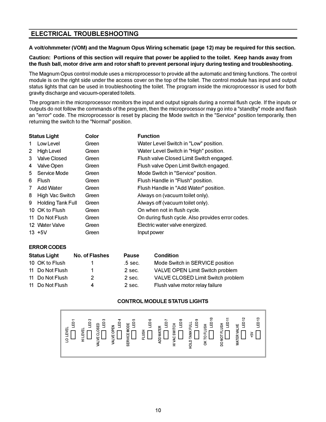
CONTROL MODULE STATUS LIGHTS
LEVEL | LED 1 |
| |
LO |
|
|
LEVEL | LED 2 |
| |
HI |
|
|
CLOSED | LED 3 |
| |
VALVE |
|
|
OPEN | LED 4 |
| |
VALVE |
|
|
MODE | LED 5 |
SERVICE |
|
|
FLUSH![]() LED 6
LED 6
WATER | LED 7 |
| |
ADD |
|
|
SWITCH | LED 8 |
| |
HI VAC |
|
|
FULL | LED 9 |
HOLD TANK |
|
| |
|
FLUSH | LED 10 |
| |
OK TO |
|
|
FLUSH | LED 11 |
| |
DO NOT |
|
|
VALVE | LED 12 |
| |
WATER |
|
|
+5V![]()
![]() LED 13
LED 13
10