6.9.6Schema elettrico
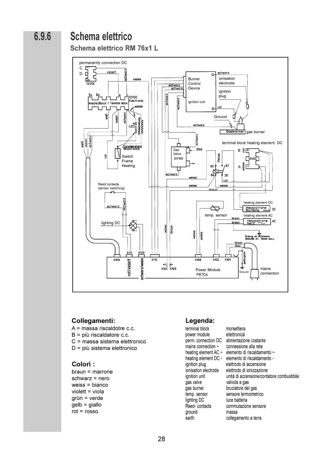
Schema elettrico RM 76x1 L
permanently connection DC C
D
Burner ionisation
Control electrode
Device
ignition plug
ignition unit
Ground
gas burner
terminal block heating element DC
GasB
Switch | Valve |
| |
Frame |
|
Heating | A |
|
Reed contacts (sensor switching)
|
| heating element DC |
|
|
|
temp. sensor |
|
|
| heating element AC | |
|
|
|
lighting DC
|
|
|
| mains |
Power Module |
|
|
| |
| Ground | |||
|
| connection | ||
|
|
| ||
|
|
|
| |
|
|
| ||
|
|
|
|
|
Collegamenti:
A = massa riscaldotre c.c. B = più riscaldatore c.c.
C = massa sistema elettronico D = più sistema elettronico
Colori :
braun = marrone schwarz = nero weiss = bianco violett = viola grün = verde gelb = giallo rot = rosso
Legenda:
terminal block | morsettiera |
power module | ellettronicá |
perm. connection DC | alimentazione costante |
mains connection ~ | connessione alla rete |
heating element AC ~ | elemento di riscaldamento ~ |
heating element DC - | elemento di riscaldamento - |
ignition plug | elettrodo di accensione |
ionisation electrode | elettrodo di ionizzazione |
ignition unit | unità di accensione/contatore combustibile |
gas valve | valvola a gas |
gas burner | bruciatore del gas |
temp. sensor | sensore termometrico |
lighting DC | luce batteria |
Reed- contacts | commutazione sensore |
ground | massa |
earth | collegamento a terra |
28