RIP FENCE OPERATION
AND ADJUSTMENTS
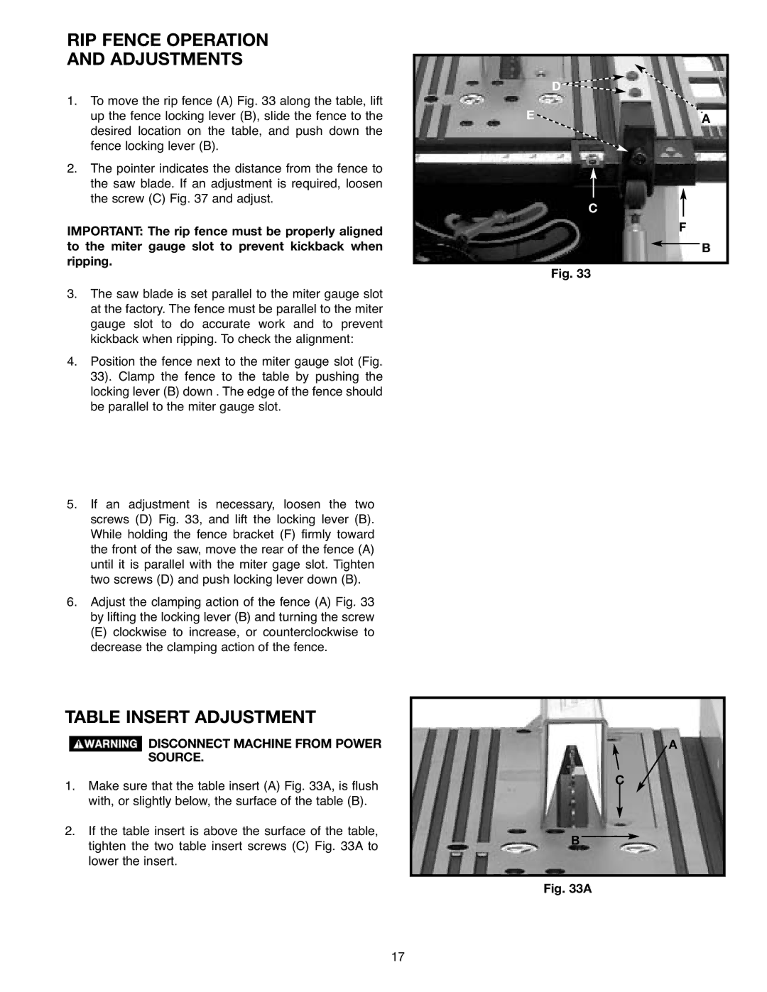
1.To move the rip fence (A) Fig. 33 along the table, lift up the fence locking lever (B), slide the fence to the desired location on the table, and push down the fence locking lever (B).
2.The pointer indicates the distance from the fence to the saw blade. If an adjustment is required, loosen the screw (C) Fig. 37 and adjust.
IMPORTANT: The rip fence must be properly aligned to the miter gauge slot to prevent kickback when ripping.
3.The saw blade is set parallel to the miter gauge slot at the factory. The fence must be parallel to the miter gauge slot to do accurate work and to prevent kickback when ripping. To check the alignment:
4.Position the fence next to the miter gauge slot (Fig. 33). Clamp the fence to the table by pushing the locking lever (B) down . The edge of the fence should be parallel to the miter gauge slot.
5.If an adjustment is necessary, loosen the two screws (D) Fig. 33, and lift the locking lever (B). While holding the fence bracket (F) firmly toward the front of the saw, move the rear of the fence (A) until it is parallel with the miter gage slot. Tighten two screws (D) and push locking lever down (B).
6.Adjust the clamping action of the fence (A) Fig. 33 by lifting the locking lever (B) and turning the screw
(E)clockwise to increase, or counterclockwise to decrease the clamping action of the fence.
TABLE INSERT ADJUSTMENT
![]() DISCONNECT MACHINE FROM POWER SOURCE.
DISCONNECT MACHINE FROM POWER SOURCE.
1.Make sure that the table insert (A) Fig. 33A, is flush with, or slightly below, the surface of the table (B).
2.If the table insert is above the surface of the table, tighten the two table insert screws (C) Fig. 33A to lower the insert.
D![]()
E![]() A
A
C
F
B
Fig. 33
A
C
B ![]()
Fig. 33A
17