UNPACKING AND CLEANING
Carefully unpack the machine and all loose items from the shipping container(s). Remove the protective coating from all unpainted surfaces. This coating may be removed with a soft cloth moistened with kerosene (do not use acetone, gasoline or lacquer thinner for this purpose). After cleaning, cover the unpainted surfaces with a good quality household floor paste wax.
ASSEMBLY
ASSEMBLY TOOLS REQUIRED | * 13mm wrench for stand bolts | |
* 10mm wrench for splitter assembly bolts | ||
(None supplied) | ||
* Straight edge and/or framing square for adjustments | ||
* Phillips head screw driver | ||
|
ASSEMBLY TIME ESTIMATE - 1 hour
ELEVATING AND SUPPORTING SURFACES FOR A SAW WITH NO STAND
![]() THE SAW MUST BE PROPERLY SECURED TO A SUPPORTING SURFACE. ALSO, FAILURE TO PROVIDE A SAWDUST
THE SAW MUST BE PROPERLY SECURED TO A SUPPORTING SURFACE. ALSO, FAILURE TO PROVIDE A SAWDUST
![]() DISCONNECT MACHINE FROM POWER SOURCE.
DISCONNECT MACHINE FROM POWER SOURCE.
The saw must be elevated enough for sawdust to fall through the bottom of the saw and not build up around the motor.
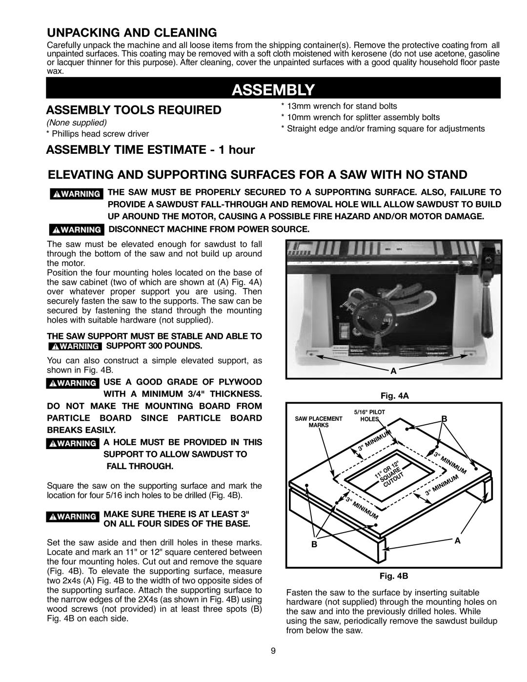
Position the four mounting holes located on the base of the saw cabinet (two of which are shown at (A) Fig. 4A) over whatever proper support you are using. Then securely fasten the saw to the supports. The saw can be secured by fastening the stand through the mounting holes with suitable hardware (not supplied).
THE SAW SUPPORT MUST BE STABLE AND ABLE TO
![]() SUPPORT 300 POUNDS.
SUPPORT 300 POUNDS.
You can also construct a simple elevated support, as shown in Fig. 4B.
![]() USE A GOOD GRADE OF PLYWOOD WITH A MINIMUM 3/4" THICKNESS.
USE A GOOD GRADE OF PLYWOOD WITH A MINIMUM 3/4" THICKNESS.
DO NOT MAKE THE MOUNTING BOARD FROM PARTICLE BOARD SINCE PARTICLE BOARD BREAKS EASILY.
![]() A HOLE MUST BE PROVIDED IN THIS SUPPORT TO ALLOW SAWDUST TO FALL THROUGH.
A HOLE MUST BE PROVIDED IN THIS SUPPORT TO ALLOW SAWDUST TO FALL THROUGH.
Square the saw on the supporting surface and mark the location for four 5/16 inch holes to be drilled (Fig. 4B).
MAKE SURE THERE IS AT LEAST 3"
ON ALL FOUR SIDES OF THE BASE.
Set the saw aside and then drill holes in these marks. Locate and mark an 11" or 12" square centered between the four mounting holes. Cut out and remove the square (Fig. 4B). To elevate the supporting surface, measure two 2x4s (A) Fig. 4B to the width of two opposite sides of the supporting surface. Attach the supporting surface to the narrow edges of the 2X4s (as shown in Fig. 4B) using wood screws (not provided) in at least three spots (B) Fig. 4B on each side.
![]() A
A
Fig. 4A
SAW PLACEMENT |
| 5/16" PILOT |
|
|
| B | ||
| HOLES |
|
|
|
| |||
MARKS |
|
|
|
|
|
|
|
|
|
| 3" | MINIMUM |
|
|
|
| |
|
|
|
|
|
| 3" |
| |
|
|
|
|
|
|
| MINIMUM | |
|
|
|
| OR | 12" |
|
| |
|
|
| 11" |
|
|
| ||
|
|
|
|
|
|
|
| |
|
|
| SQUARE |
|
|
| ||
|
|
|
| CUTOUT |
| MINIMUM | ||
|
|
|
|
|
| 3" | ||
| 3" | MINIMUM |
|
|
|
|
| |
|
|
|
|
|
|
| ||
B |
|
|
|
|
|
|
| A |
|
|
|
|
|
|
|
| |
Fig. 4B
Fasten the saw to the surface by inserting suitable hardware (not supplied) through the mounting holes on the saw and into the previously drilled holes. While using the saw, periodically remove the sawdust buildup from below the saw.
9