DM 2610921728 | 8/23/05 | 9:15 AM | Page 10 |
|
|
| ||||
|
|
|
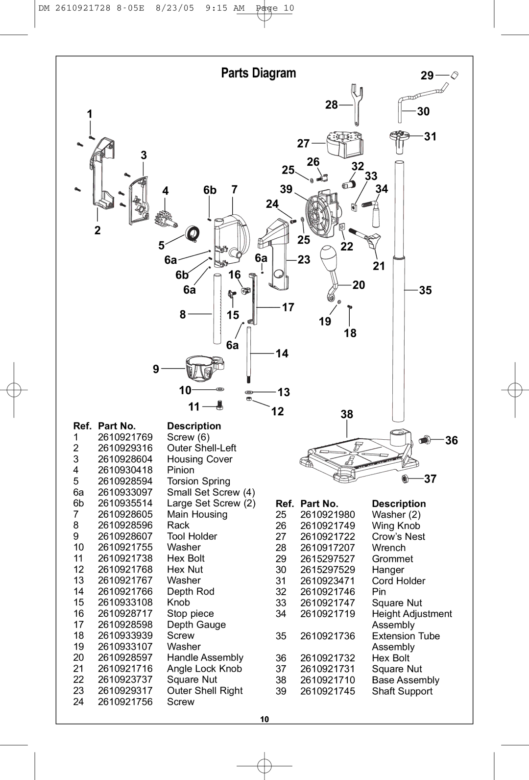
| Parts Diagram | 28 |
| 29 | |||
| 1 |
|
|
|
|
|
|
| 30 | |
| 3 |
|
|
|
|
|
| 2726 | 32 | 31 |
|
| 4 | 6b | 7 |
| 25 | 3334 | |||
|
|
| 24 | 39 |
|
| ||||
| 2 |
|
|
|
|
|
|
|
| |
| 5 |
|
| 6a |
| 25 | 22 |
| ||
|
|
|
|
| 21 | |||||
|
|
| 6a |
| 16 |
| 23 |
| ||
|
|
| 6b |
|
|
|
| 20 | 35 | |
|
|
| 6a |
| 15 |
| 17 |
| ||
|
|
| 8 |
|
| 19 | 18 |
| ||
|
|
|
|
| 6a | 14 |
| |||
|
| 9 |
|
|
|
|
| |||
|
|
|
|
|
|
|
| |||
|
| 10 |
|
| 13 |
|
|
| ||
|
|
|
|
|
|
|
| |||
Ref. Part No. |
| 11 |
|
| 12 |
| 38 |
| ||
| Description |
|
|
| ||||||
1 | 2610921769 |
| Screw (6) |
|
|
|
|
| 36 | |
2 | 2610929316 |
| Outer |
|
|
|
| |||
3 | 2610928604 |
| Housing Cover |
|
|
|
|
| ||
4 | 2610930418 |
| Pinion |
|
|
|
|
|
| 37 |
5 | 2610928594 |
| Torsion Spring |
|
|
|
| |||
6a | 2610933097 |
| Small Set Screw (4) | Ref. Part No. |
| Description | ||||
6b | 2610935514 |
| Large Set Screw (2) |
| ||||||
7 | 2610928605 |
| Main Housing | 25 | 2610921980 | Washer (2) | ||||
8 | 2610928596 |
| Rack |
|
| 26 | 2610921749 | Wing Knob | ||
9 | 2610928607 |
| Tool Holder |
| 27 | 2610921722 | Crow’s Nest | |||
10 | 2610921755 |
| Washer |
|
| 28 | 2610917207 | Wrench | ||
11 | 2610921738 |
| Hex Bolt |
| 29 | 2615297527 | Grommet | |||
12 | 2610921768 |
| Hex Nut |
|
| 30 | 2615297529 | Hanger | ||
13 | 2610921767 |
| Washer |
|
| 31 | 2610923471 | Cord Holder | ||
14 | 2610921766 |
| Depth Rod |
| 32 | 2610921746 | Pin | |||
15 | 2610933108 |
| Knob |
|
| 33 | 2610921747 | Square Nut | ||
16 | 2610928717 |
| Stop piece |
| 34 | 2610921719 | Height Adjustment | |||
17 | 2610928598 |
| Depth Gauge |
| 35 | 2610921736 | Assembly | |||
18 | 2610933939 |
| Screw |
|
| Extension Tube | ||||
19 | 2610933107 |
| Washer |
|
| 36 | 2610921732 | Assembly | ||
20 | 2610928597 |
| Handle Assembly | Hex Bolt | ||||||
21 | 2610921716 |
| Angle Lock Knob | 37 | 2610921731 | Square Nut | ||||
22 | 2610923737 |
| Square Nut |
| 38 | 2610921710 | Base Assembly | |||
23 | 2610929317 |
| Outer Shell Right | 39 | 2610921745 | Shaft Support | ||||
24 | 2610921756 |
| Screw |
|
| 10 |
|
|
|
|
|
|
|
|
|
|
|
|
|
| |