101
Appendix C - Differential amplifier connection
The differential amplifier is provided for your optional use. It can be used for buffering, inverting or elimination of common mode signals.
The differential amplifier inputs are available at terminals H/R-9b,E-J3/1, H/R-10b,E-J3/2. Terminal H/R-10b,E-J3/2 is the inverting input, terminal H/R- 9b,E-J3/1 is the non-inverting input. The output is on terminal H/R-11b,E-J3/3. The differential amplifier can be internally connected to the summing junction by inserting R800.
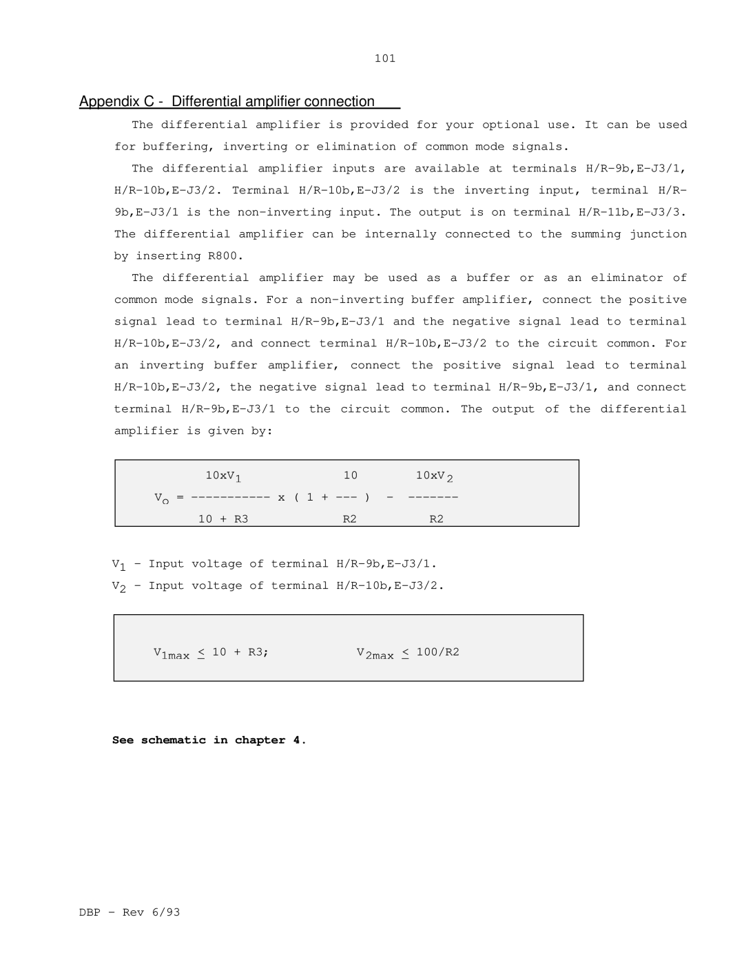
The differential amplifier may be used as a buffer or as an eliminator of common mode signals. For a non-inverting buffer amplifier, connect the positive signal lead to terminal H/R-9b,E-J3/1 and the negative signal lead to terminal H/R-10b,E-J3/2, and connect terminal H/R-10b,E-J3/2 to the circuit common. For an inverting buffer amplifier, connect the positive signal lead to terminal H/R-10b,E-J3/2, the negative signal lead to terminal H/R-9b,E-J3/1, and connect terminal H/R-9b,E-J3/1 to the circuit common. The output of the differential amplifier is given by:
10xV1 | 10 | 10xV 2 |
Vo = ----------- x ( 1 + --- ) | - ------- |
10 + R3 | R2 | R2 |
V1 - Input voltage of terminal H/R-9b,E-J3/1.
V2 - Input voltage of terminal H/R-10b,E-J3/2.
V1max < 10 + R3; | V2max < 100/R2 |
| |
See schematic in chapter 4.
DBP - Rev 6/93