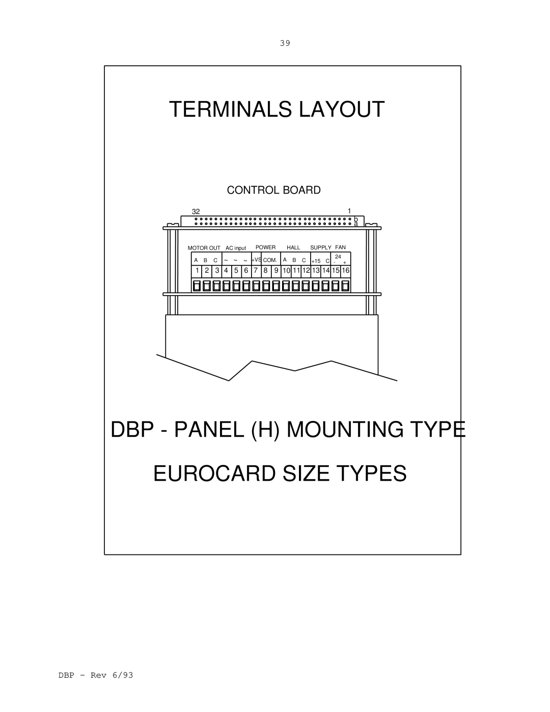
0 Rev 6/93
DBP - Rev 6/93
ELMO-WARRANTYPERFORMANCE
from shipment by the manufacturing plant
How to use this manual - Flow Chart
TABLE OF CONTENTS
6.5.1
Appendix B - Adding a velocity feedback
1.Description
Analog Section Standard Features
2.Type Designation
DBP F- 24 / 270 R R O
3. Technical Specification
3.1Digital I/O specification
General
Digital Inputs
Digital Outputs
DIGITAL OUTPUTS
DBP - Rev 6/93
DIGITAL INPUTS
I1 I2 I3 I4 I5 INDEX SLAVE
3.2 Analog input specification
ANALOG INPUT
3.3.1Encoder
3.3Sensors specification
3.3.2Resolver
ENCODER INPUTS
CH B
CH B
CH A
3.4.1RS232 Configuration
3.4.2RS485 Configuration
3.5 Battery backup
3.4Communication
RS485/RS232
COMMUNICATION
8 ohm
4.1 RS485 and Checksum Protocol
4. System Operation
4.2 Current Control
Error amplifier
Current amplifier x2 Current feedback CFM
4.3 Digital current limits
4.3.1Time dependent peak current limit
4.4 Digital position and speed control
Control Modes Holding Modes Start Modes
Program Mode Termination Modes Status reporting
Define origin modes
Control Modes
Holding Modes
Position Mode
Velocity Mode
Direct command
Start Modes
Program Mode
Termination Modes
Hardware signal
Status Reporting
Define origin modes
Communication
4.5 Operation of the shunt regulator
SHUNT specifications
4.6 Commutation signals format
4.7.3Temperature protection
4.7.4Internal power supply failure
4.7.6Low back-upBattery voltage
4.7 Protective functions
DBP 3U - BLOCK DIAGRAM
DCB BLOCK DIAGRAM
DBP - Rev 6/93
DCB COMPONENTS LAYOUT
DBP - Rev 6/93
DCB RESOLVER OPTION BLOCK DIAGRAM
RESOLVER BOARD COMPONENTS LAYOUT
U25
200
60 67 61 R R R R R R R R R R
5. Terminal Description
FUNCTION
Control board
Control board - cont
H & R
H & R
RACK VERSION - 3U SIZE
POWER BOARD
TERMINALS OF DBP
CONTROL BOARD
TERMINALS LAYOUT
CONTROL BOARD
DBP - PANEL H MOUNTING TYPE EUROCARD SIZE TYPES
+FAN
DBP-6URACK TYPE CONNECTORS
CONTROL
AA C
2 A C
POWER TERMINALS FOR MBA-DBP/3U
POWER TERMINALS FOR MBA-DBP/6U
Signals connector - J1 MBA-DBP/3Uand MBA-DBP/6U
Signals connector - J3 MBA-DBP/3Uand MBA-DBP/6U
Function
Function
Function
Signals connector - J6 - cont
Signals connector - J8 MBA-DBP/3Uand MBA-DBP/6U
MBA - DBP/3U
J3 J2
7 6 5 4 3 2 1 15 16 J7
6 J1
MBA-DBP/6U
SO +VS POW. COM AC AC AC M3 M2 M1
5.3 Terminals for DBP mounted in ENCD
Signals connector - J1 MBA-DBP/3UEand MBA-DBP/6UE
Signals connector - J3 MBA-DBP/3UEand MBA-DBP/6UE
Function
Vil 1V, Vih 2.4V, Maximum input voltage +30VDC
57 Signals connector - J4 - cont
DBP - Rev 6/93
Function
Signals connector - J6 - cont
Signals connector - J8 MBA-DBP/3UEand MBA-DBP/6UE
MBA-DBP/3UE
MBA-DBP/6UE
ground only when ISOLATED amplifier
MC GND AC
AC POW +VS SO
RS232
5.4 Communication Port Connector
RS485
6. Installation procedures 6.1 Mounting
6.2 Wiring
1.2 x VACmin VAC 0.9 x VACmax
6.4 AC power supply
6.3 Load inductance
6.5Wiring diagrams
6.5.1Motors windings
6.5.2AC power wiring
Power common
Ground
Control common Motor chassis Amplifiers heatsink
Do not ground
AC DBP + I option
Isolating transformer
DIRECT CONNECTION TO THE THREE PHASE MAINS Fuse
DC power common Control common Heatsink
CONNECTING MORE THAN ONE DBP
NOTE DC POWER TERMINALS ARE
ISOLATING
SINGLE PHASE CONNECTION
DC power common Control common Heatsink
single phase connection
Fuse Fuse External capacitance
DOUBLE EUROCARD SIZE ONLY
CONNECTING THE EXTERNAL SHUNT RESISTOR
DBP - Rev 6/93
6.5.3Hall sensors wiring
HALL SENSORES CONNECTION
RS232 COMMUNICATION
6.5.4 RS232 Communication wiring
SYMBOLS
6.5.5RS485 Communication wiring
RS 485 COMMUNICATION
RS485 COMMUNICATION
6.5.6Main encoder wiring
ENCODER CONNECTION
DIFFERENTIAL ENCODER CONNECTION
SYMBOLS
6.5.7Resolver wiring
RESOLVER CONNECTION
6.5.8Auxiliary encoder wiring
AUXILIARY ENCODER CONNECTION
DIFFERENTIAL AUXILIARY
ENCODER CONNECTION
INPUT CONNECTION
6.5.9Pulse/Direction signals wiring
PULSE & DIRECTION INPUT CONNECTION
DIFFERENTIAL PULSE & DIRECTION
7. Start - Up Procedures
7.1Common procedures for all amplifiers types
7.1.1Commutation signals format
7.1.2CFM function
7.1.4Setting the auxiliary position input format
7.1.5Selecting the communication bus
7.1.6Preparing the automatic baud rate selection
When using an Optical encoder
7.2 Setting the main optical encoder format
7.3 Setting the R/D circuit
Oscillator
When Vinrms 2V, install R193=R194=100 ohm
R193 = R194 = Vinrms - 2 - Rstator
Kohm
Rstator in Kohm
Resolution
Encoder resolution
S = resolution of converter 2 10,212,or
bit =
90 HF Filter R195, R196, C61, C62
15Kohm R195=R196 30Kohm
160x103
C61 = C62 =
where p = bit per rev
=1,024 for 10 bits resolution =4,096 for 12 bits
R201 = 5.92 x 10⁷ / T x p
Kohm
92 d. R200 is given by
127
R200 =
Kohm
8. Applying power - Adjustments
Step 1 - Applying Power
Step 4 - Adjusting the current limits
Step 2 - Establishing the communication
Step 3 - Checking the feedback elements
Defining the amplifier type
Step 6 - Connecting the Motor
Step 5 - Latch mode of the protective functions
Current limit adjustments
Self Restart LM0
9. Tables and Summaries 9.1 Display diagnostics
9.2 Summary of DIP switches Power stage board
2 poles DIP switch
9 poles DIP switch
4 poles DIP switch for Resolver
Appendix A - Current loop response
Reference input signal
C1 too large / R4 too small Critically damped
C1 too small / R4 too large
Fig. A-1 Typical current response waveforms
Appendix B - Adding a velocity feedback
THIS PAGE IS BLANK
Appendix C - Differential amplifier connection
See schematic in chapter
DIMENSIONAL DRAWINGS
PANEL H, DBP1
BATTERY
DBP1 - TOP VIEW
12.5
52.5
DBP1 - SIDE VIEW
18.6
111.76
DBP1 - SIDE VIEW
32.3
PANEL H, DBP2
DBP2 - TOP VIEW
BATTERY
DBP2 - SIDE VIEW
1 2 ON
85.5
51.2
DBP2 - SIDE VIEW
111.76
32.3
9.64
DBP3 - TOP VIEW
PANEL H, DBP3
BATTERY
DETAIL A
DBP3 - SIDE VIEW
9.64
14.64
14.64
DBP3 - SIDE VIEW
DBP - Rev 6/93
245.11
111.76
PANEL H, DBP4
DBP4 - TOP VIEW
BATTERY
DBP4 - SIDE VIEW
SIDE VIEW
9.64
14.64
DBP4 - SIDE VIEW
DBP - Rev 6/93
DBP6 - TOP VIEW
PANEL H, DBP6
FRONT VIEW
DBP6 - SIDE VIEW
130
DBP6 - SIDE VIEW
DBP RACK MOUNTING 3U/ 13T
SIDE VIEW
RACK 3U/13T
65.84
DBP RACK MOUNTING 3U/ 13T
SIDE VIEW
111.76
32.3
FRONT PANEL FOR DBP 3U/13T
POWER
DBP RACK MOUNTING 3U/20T
RACK 3U/20T
SIDE VIEW
83.54
DBP RACK MOUNTING 3U/ 20T
SIDE VIEW
111.76
32.3
FRONT PANEL FOR DBP 3U/ 20T
101.4
128.7
POWER
SIDE VIEW
DBP RACK MOUNTING 6U/14T
RACK 6U/14T
DBP RACK MOUNTING 6U/14T
SIDE VIEW
70.92
FRONT PANEL FOR DBP 6U/14T
POWER
RACK 6U/21T
DBP RACK MOUNTING 6U/21T
SIDE VIEW
POWER
FRONT PANEL FOR DBP 6U/21T
E L M
ENCD - 3U
ENCD - 3U
ALL DIMENSIONS ARE IN mm
Standard Sizes
ENCD - 6U
ENCD - 6U
FRONT VIEW
SIDE VIEW
EXTERNAL SHUNT RESISTOR
EXTERNAL SHUNT RESISTOR ESR
293.7
List of ELMO Service Centers
ISRAEL
U.S.A
EUROPE
FINLAND
FRANCE
GERMANY
ITALY