47
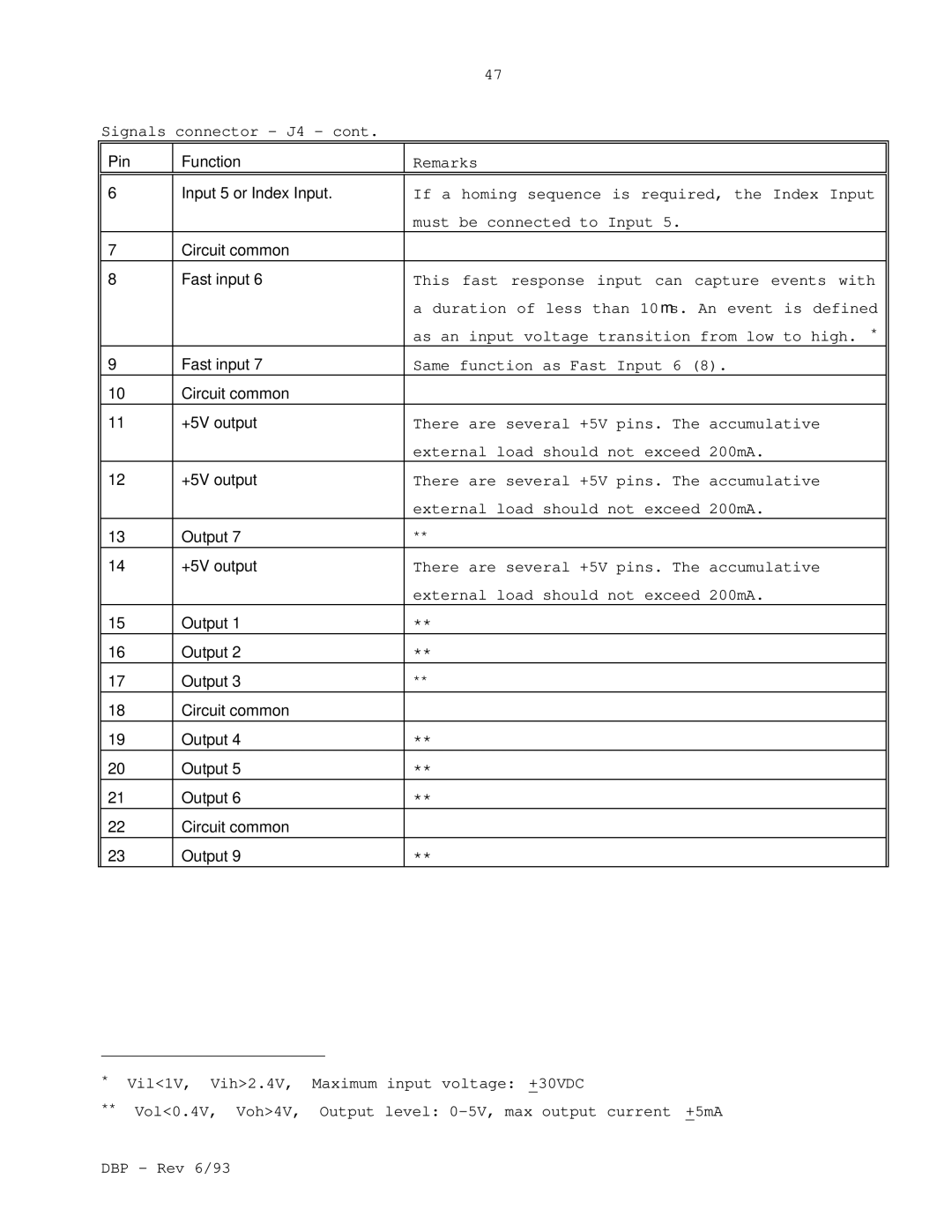
Signals connector - J4 - cont.
Pin | Function | Remarks |
|
|
|
6 | Input 5 or Index Input. | If a homing sequence is required, the Index Input |
|
| must be connected to Input 5. |
7 | Circuit common |
|
8 | Fast input 6 | This fast response input can capture events with |
|
| a duration of less than 10 μs. An event is defined |
|
| as an input voltage transition from low to high. * |
9 | Fast input 7 | Same function as Fast Input 6 (8). |
10 | Circuit common |
|
11 | +5V output | There are several +5V pins. The accumulative |
|
| external load should not exceed 200mA. |
12 | +5V output | There are several +5V pins. The accumulative |
|
| external load should not exceed 200mA. |
13 | Output 7 | ** |
14 | +5V output | There are several +5V pins. The accumulative |
|
| external load should not exceed 200mA. |
15 | Output 1 | ** |
16 | Output 2 | ** |
17 | Output 3 | ** |
18 | Circuit common |
|
19 | Output 4 | ** |
20 | Output 5 | ** |
21 | Output 6 | ** |
22 | Circuit common |
|
23 | Output 9 | ** |
*Vil<1V, Vih>2.4V, Maximum input voltage: +30VDC
**Vol<0.4V, Voh>4V, Output level: