Manuals
/
Elmo
/
Home Audio
/
Stereo Amplifier
Elmo
DBP SERIES
manual
DBP6 Side View
Models:
DBP SERIES
1
117
134
134
Download
134 pages
61.8 Kb
114
115
116
117
118
119
120
121
Specification
DBP 3U Block Diagram
Hardware signal
Wiring
Warranty
Dimension
1 RS232 Configuration
Direct command
DBP-6U Rack Type Connectors
Low back-up Battery voltage
Page 117
Image 117
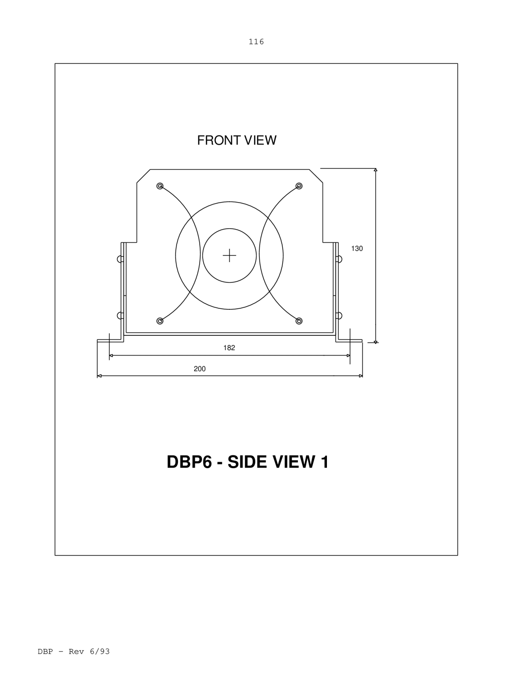
116
FRONT VIEW
130
182
200
DBP6 - SIDE VIEW 1
DBP - Rev 6/93
Page 116
Page 118
Page 117
Image 117
Page 116
Page 118
Contents
Rev 6/93 DBP Rev 6/93
ELMO-WARRANTY Performance
How to use this manual Flow Chart
Table of Contents
Step
Panel H, DBP1
Description
Analog Section Standard Features
Type Designation
Digital Section Standard Features
Technical Specification
General
Digital I/O specification
Digital Inputs
Digital Outputs
Digital Outputs
Digital Inputs
Analog Input
Analog input specification
Resolver Option Feature
Sensors specification
Encoder
Resolver
Encoder Inputs
2 RS485 Configuration
1 RS232 Configuration
Battery backup
Communication
Communication
Current Control
System Operation RS485 and Checksum Protocol
CFM
Time dependent peak current limit
Digital current limits
Digital position and speed control
Velocity Mode
Position Mode
Servo Mode
Motor Off Mode
Latch Mode
Direct command
Program
Input condition
Hardware signal
Digit display
Auto restart
Operation of the shunt regulator
Shunt specifications
Commutation signals format
Internal power supply failure
Temperature protection
Low back-up Battery voltage
Short circuit protection
DBP 3U Block Diagram
DCB Block Diagram
DCB Components Layout
DCB Resolver Option Block Diagram
Resolver Board Components Layout
Function
Terminal Description
8ac
4ac,2ac
14ac,12ac
20ac,18ac
Page
Page
Control board
Function Remarks 24a Auxiliary Encoder Complementary Input
Mode 24b Resolver
Direction Input For Pulse
Reference voltage to the resolver must be
Terminals of DBP
Terminals Layout
DBP Panel H Mounting Type Double Eurocard Size Type
DBP-6U Rack Type Connectors
Mother Boards terminals MBA-DBP/3U and MBA-DBP/6U
Power Terminals for MBA-DBP/3U
Power Terminals for MBA-DBP/6U
Circuit common
DBP Rev 6/93
Signals connector J3
Signals connector J4
Pin Function Remarks Output
J1A, FAN Terminals MBA-DBP/6U only
Page
MBA DBP/3U
MBA-DBP/6U
Terminal Function
Terminals for DBP mounted in Encd
Circuit common
DBP Rev 6/93
Signals connector J3
Signals connector J4
Pin Function Remarks Output
Page
Page
MBA-DBP/3UE
MBA-DBP/6UE
Communication Port Connector
RS232
RS485
Wiring
Installation procedures Mounting
Load inductance
AC power supply
Motors windings
Wiring diagrams
AC power wiring
Guide lines for connecting non-isolated AC supplies
Ground
Do not ground
AC DBP + I option
AC NON-ISOLATED DBP
AC DBP
Isolating Transformer
NON
Single Phase Connection
AC DBP AC
Hall Sensores Connection
Hall sensors wiring
RS232 Communication
4 RS232 Communication wiring
RS 485 Communication
5 RS485 Communication wiring
RS485 Communication
Differential Encoder Connection
Main encoder wiring
Resolver Connection
Resolver wiring
Differential Auxiliary Encoder Connection
Auxiliary encoder wiring
Input Connection
Pulse/Direction signals wiring
Commutation signals format
CFM function
Abort logic
When using an Optical encoder
Setting the auxiliary position input format
When using Pulse and Direction signals
Selecting the communication bus
Setting the main optical encoder format
Setting the R/D circuit
Converter
Oscillator Frequency/Amplitude Selection R228,R233
Oscillator
Page
OFF
Page
Page
Page
Applying Power
Applying power Adjustments
Establishing the communication
Adjusting the current limits
Checking the feedback elements
Defining the amplifier type
Connecting the Motor
Latch mode of the protective functions
Current limit adjustments
Self Restart LM0
Tables and Summaries Display diagnostics
Summary of DIP switches Power stage board Poles DIP switch
Control stage board Poles DIP switch
Poles DIP switch for Resolver
Appendix a Current loop response
Fig. A-1 Typical current response waveforms DBP Rev 6/93
Appendix B Adding a velocity feedback
This page is Blank
Appendix C Differential amplifier connection
See schematic in chapter
Dimensional Drawings
DBP1 TOP View
104
111.76 32.3
DBP2 TOP View
107
108
DBP3 TOP View
110
DBP3 Side View
DBP4 TOP View
DBP4 Side View
DBP4 Side View
DBP6 TOP View
DBP6 Side View
117
DBP6 Side View
DBP Rack Mounting 3U/ 13T
119
120
Front Panel for DBP 3U/13T
DBP Rack Mounting 3U/20T
122
101.4
128.7
123
DBP Rack Mounting 6U/14T Side View
DBP Rack Mounting 6U/14T Side View
70.92
262
126
DBP Rack Mounting 6U/21T Side View
128
Front Panel for DBP 6U/21T
Encd 3U
Encd 3U
Encd 6U
Encd 6U
External Shunt Resistor ESR
Israel
List of Elmo Service Centers
Finland
Top
Page
Image
Contents