50
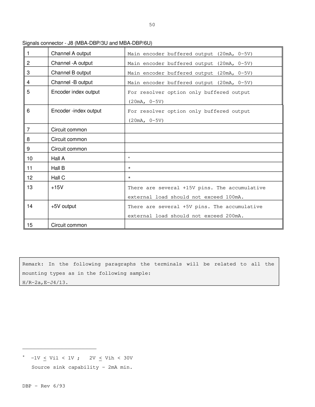
Signals connector - J8
1 | Channel A output | Main encoder buffered output (20mA, | |
2 | Channel | Main encoder buffered output (20mA, | |
3 | Channel B output | Main encoder buffered output (20mA, | |
4 | Channel | Main encoder buffered output (20mA, | |
5Encoder index output For resolver option only buffered output (20mA,
6Encoder
7 | Circuit common |
|
8 | Circuit common |
|
9 | Circuit common |
|
10 | Hall A | * |
11 | Hall B | * |
12 | Hall C | * |
13 | +15V | There are several +15V pins. The accumulative |
|
| external load should not exceed 100mA. |
14 | +5V output | There are several +5V pins. The accumulative |
|
| external load should not exceed 200mA. |
15 | Circuit common |
|
Remark: In the following paragraphs the terminals will be related to all the mounting types as in the following sample:
*