Manuals
/
Drolet
/
Household Appliance
/
Indoor Fireplace
Drolet
7000 MVRLC, 36C03U TYPE 139
manual
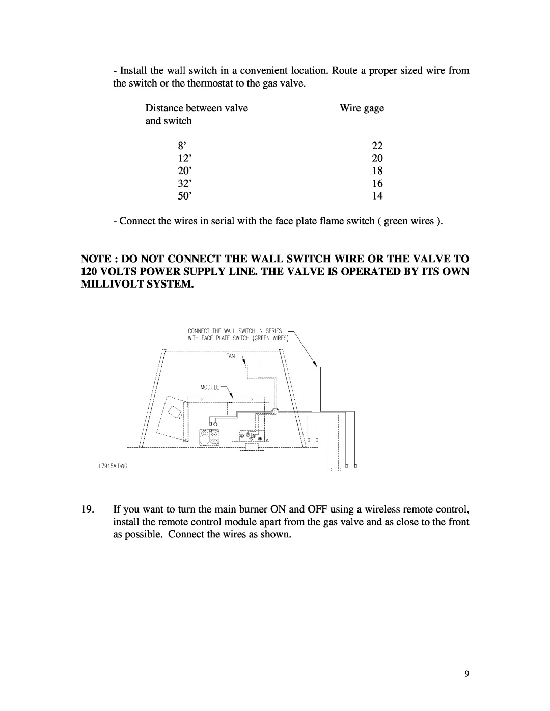
Distance between valve
Models:
7000 MVRLC
36C03U TYPE 139
1
10
21
21
Download
21 pages
63.08 Kb
7
8
9
10
11
12
13
14
Specs
Install
Warranty
Maintenance
Replacement Parts
Safety
Page 10
Image 10
Page 9
Page 11
Page 10
Image 10
Page 9
Page 11
Contents
FIREPLACE GAS INSERT
INSTALLATION AND OPERATING INSTRUCTIONS
FOR YOUR SAFETY
FOR YOUR SAFETY
TABLE OF CONTENTS
GENERAL INFORMATION
KEEP THESE INSTRUCTIONS FOR FUTURE REFERENCE
DO NOT MODIFY THIS APPLIANCE
SPECIFICATIONS
TOP, SIDE AND FRONT VIEWS
INSTALLATION
11.Secure the liner to the 4” connector on the top of the ULTRA FLAME with three metal screws
WARNING DO NOT USE OPEN FLAME TO CHECK LEAKS
Distance between valve
25.Install a cap on the liner
GLASS FRONT REMOVAL CLEANING AND INSTALLATION
BURNER REMOVAL AND INSTALLATION
LOG INSTALLATION
FACE PLATE ASSEMBLY AND INSTALLATION
INSTALLATIONS
REFRACTORY PANELS INSTALLATIONS
EMBERS KIT INSTALLATIONS
SHUTDOWN INSTRUCTIONS
OPERATING INSTRUCTIONS LIGHTING INSTRUCTIONS
FAN OPERATION
MAINTENANCE INSTRUCTIONS
PILOT BURNER ADJUSTMENT
REPLACEMENT PARTS
OPTIONAL PARTS
LIMITED 5 YEARS WARRANTY
Top
Page
Image
Contents