Progressive Scan Display Interface specifications
DVDO Progressive Scan Display Interface (PDI) is an advanced technology designed to enhance video quality and user experience in display systems. It serves as a bridge between source devices, like DVD players or gaming consoles, and output displays such as televisions and projectors. The main purpose of the PDI is to provide a better visual experience by minimizing motion artifacts, enhancing color accuracy, and improving overall image clarity.One of the key features of DVDO PDI technology is its progressive scan capability. Unlike traditional interlaced scanning methods where alternate lines of an image are displayed in each frame, progressive scanning delivers the entire image at once. This results in smoother motion and sharper images, especially beneficial for fast-paced content like sports or action movies.
Another important characteristic of DVDO PDI is its upscaling ability. The interface can take lower resolution video sources and convert them into higher quality outputs, ensuring that older video content can still look impressive on today’s high-definition displays. This upscaling feature is critical for users who still want to enjoy classic films or legacy video games without compromising on picture quality.
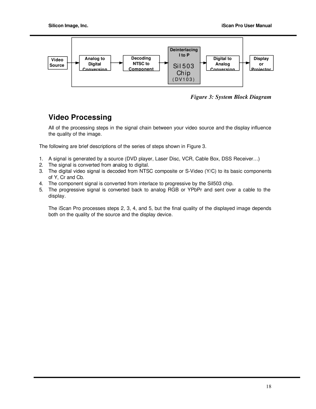
The technology also incorporates sophisticated deinterlacing algorithms that intelligently analyze video signals. These algorithms help in reducing visual artifacts such as combing and blurring, commonly found in interlaced video formats. This enhancement is particularly useful for mixed video sources, allowing seamless switching between different content types without noticeable degradation in quality.
DVDO PDI is also designed with various connectivity options to ensure compatibility with a wide range of devices. High-definition multimedia interface (HDMI) compatibility allows for easy integration with modern displays, while additional outputs can cater to older systems, making it a versatile choice for multimedia setups.
Moreover, the user-friendly features of DVDO PDI include adjustable settings for color calibration, contrast enhancement, and image scaling, allowing users to customize their viewing experience. This adaptability makes it suitable for both home theater enthusiasts and casual viewers alike.
In conclusion, the DVDO Progressive Scan Display Interface stands out with its combination of progressive scanning, upscaling, intelligent deinterlacing, and extensive connectivity options. These characteristics work together to deliver an enhanced viewing experience, ensuring that users enjoy superior video quality regardless of the source material. As technology continues to evolve, DVDO remains at the forefront of display innovations, offering solutions that cater to the diverse needs of consumers.

