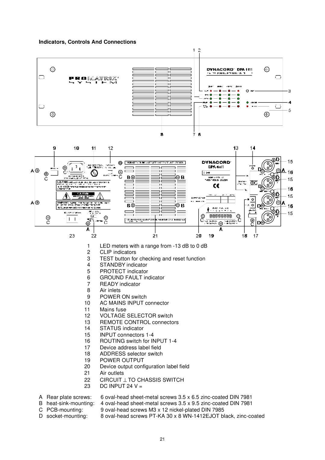
Indicators, Controls And Connections
| 1 | LED meters with a range from |
| 2 | CLIP indicators |
| 3 | TEST button for checking and reset function |
| 4 | STANDBY indicator |
| 5 | PROTECT indicator |
| 6 | GROUND FAULT indicator |
| 7 | READY indicator |
| 8 | Air inlets |
| 9 | POWER ON switch |
| 10 | AC MAINS INPUT connector |
| 11 | Mains fuse |
| 12 | VOLTAGE SELECTOR switch |
| 13 | REMOTE CONTROL connectors |
| 14 | STATUS indicator |
| 15 | INPUT connectors |
| 16 | ROUTING switch for INPUT |
| 17 | Device address label field |
| 18 | ADDRESS selector switch |
| 19 | POWER OUTPUT |
| 20 | Device output configuration label field |
| 21 | Air outlets |
| 22 CIRCUIT ⊥ TO CHASSIS SWITCH | |
| 23 DC INPUT 24 V = | |
A | Rear plate screws: | 6 |
B | 4 | |
C | 9 | |
D | 8 | |
21