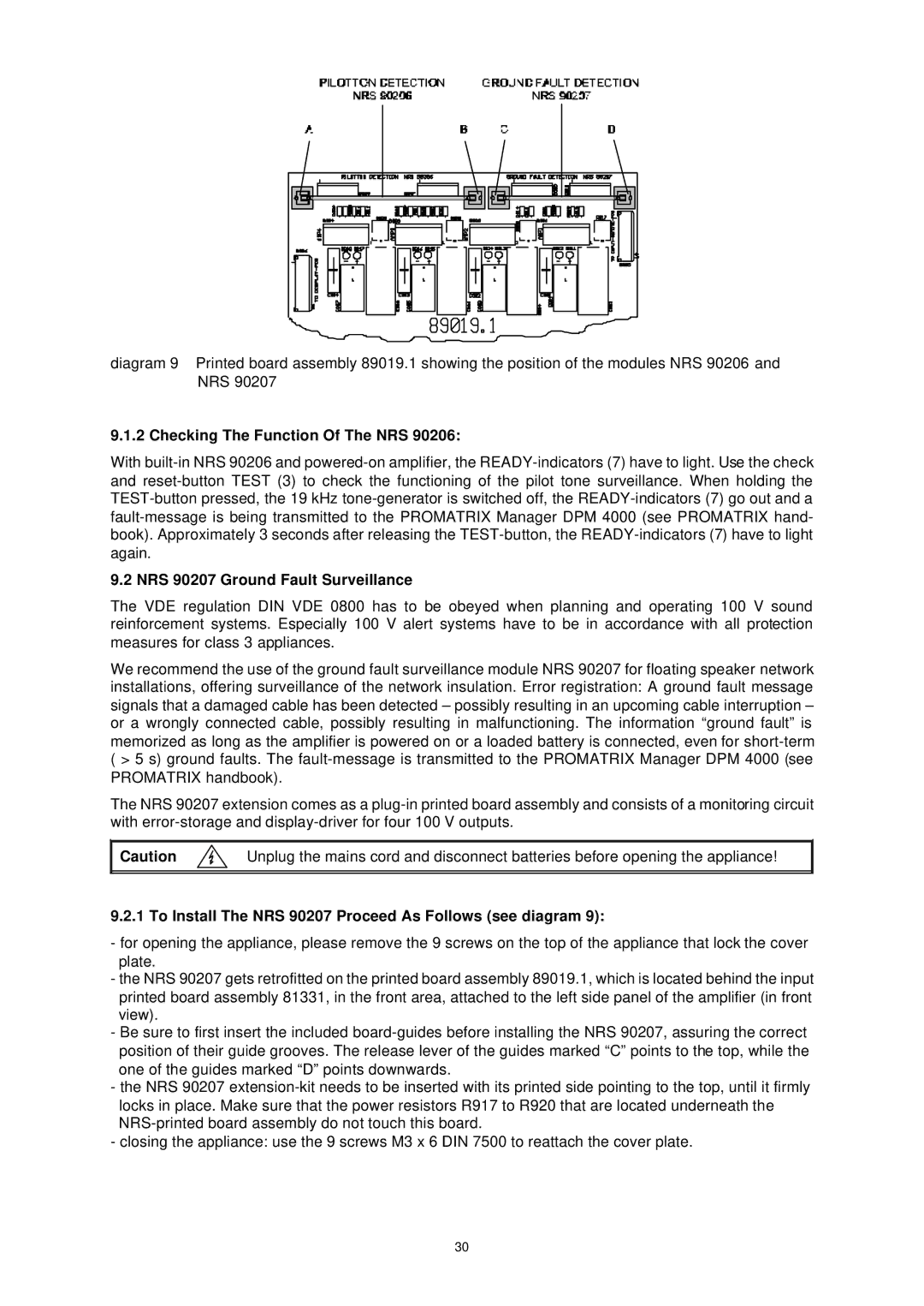
diagram 9 Printed board assembly 89019.1 showing the position of the modules NRS 90206 and NRS 90207
9.1.2 Checking The Function Of The NRS 90206:
With
9.2 NRS 90207 Ground Fault Surveillance
The VDE regulation DIN VDE 0800 has to be obeyed when planning and operating 100 V sound reinforcement systems. Especially 100 V alert systems have to be in accordance with all protection measures for class 3 appliances.
We recommend the use of the ground fault surveillance module NRS 90207 for floating speaker network installations, offering surveillance of the network insulation. Error registration: A ground fault message signals that a damaged cable has been detected – possibly resulting in an upcoming cable interruption – or a wrongly connected cable, possibly resulting in malfunctioning. The information “ground fault” is memorized as long as the amplifier is powered on or a loaded battery is connected, even for
The NRS 90207 extension comes as a
Caution |
| Unplug the mains cord and disconnect batteries before opening the appliance! |
|
|
|
9.2.1 To Install The NRS 90207 Proceed As Follows (see diagram 9):
-for opening the appliance, please remove the 9 screws on the top of the appliance that lock the cover plate.
-the NRS 90207 gets retrofitted on the printed board assembly 89019.1, which is located behind the input printed board assembly 81331, in the front area, attached to the left side panel of the amplifier (in front view).
-Be sure to first insert the included
-the NRS 90207
-closing the appliance: use the 9 screws M3 x 6 DIN 7500 to reattach the cover plate.
30