Page 2
Connecting the PowerPanel to the eLogger V3
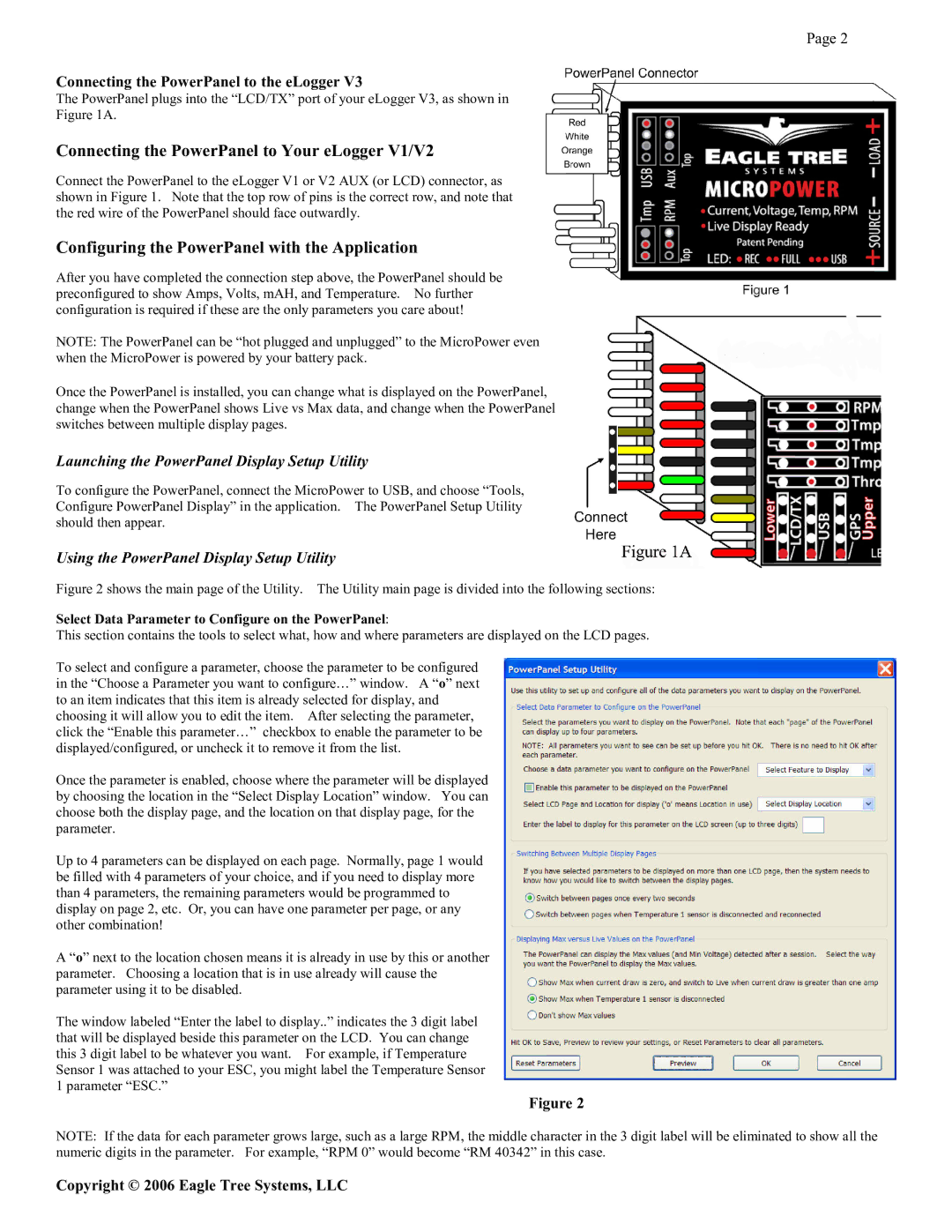
The PowerPanel plugs into the “LCD/TX” port of your eLogger V3, as shown in
Figure 1A.
Connecting the PowerPanel to Your eLogger V1/V2
Connect the PowerPanel to the eLogger V1 or V2 AUX (or LCD) connector, as shown in Figure 1. Note that the top row of pins is the correct row, and note that the red wire of the PowerPanel should face outwardly.
Configuring the PowerPanel with the Application
After you have completed the connection step above, the PowerPanel should be preconfigured to show Amps, Volts, mAH, and Temperature. No further configuration is required if these are the only parameters you care about!
NOTE: The PowerPanel can be “hot plugged and unplugged” to the MicroPower even when the MicroPower is powered by your battery pack.
Once the PowerPanel is installed, you can change what is displayed on the PowerPanel, change when the PowerPanel shows Live vs Max data, and change when the PowerPanel switches between multiple display pages.
Launching the PowerPanel Display Setup Utility
To configure the PowerPanel, connect the MicroPower to USB, and choose “Tools, Configure PowerPanel Display” in the application. The PowerPanel Setup Utility should then appear.
Using the PowerPanel Display Setup Utility
Figure 2 shows the main page of the Utility. The Utility main page is divided into the following sections:
Select Data Parameter to Configure on the PowerPanel:
This section contains the tools to select what, how and where parameters are displayed on the LCD pages.
To select and configure a parameter, choose the parameter to be configured in the “Choose a Parameter you want to configure…” window. A “o” next to an item indicates that this item is already selected for display, and choosing it will allow you to edit the item. After selecting the parameter, click the “Enable this parameter…” checkbox to enable the parameter to be displayed/configured, or uncheck it to remove it from the list.
Once the parameter is enabled, choose where the parameter will be displayed by choosing the location in the “Select Display Location” window. You can choose both the display page, and the location on that display page, for the parameter.
Up to 4 parameters can be displayed on each page. Normally, page 1 would be filled with 4 parameters of your choice, and if you need to display more than 4 parameters, the remaining parameters would be programmed to display on page 2, etc. Or, you can have one parameter per page, or any other combination!
A “o” next to the location chosen means it is already in use by this or another parameter. Choosing a location that is in use already will cause the parameter using it to be disabled.
The window labeled “Enter the label to display..” indicates the 3 digit label that will be displayed beside this parameter on the LCD. You can change this 3 digit label to be whatever you want. For example, if Temperature Sensor 1 was attached to your ESC, you might label the Temperature Sensor 1 parameter “ESC.”
Figure 2
NOTE: If the data for each parameter grows large, such as a large RPM, the middle character in the 3 digit label will be eliminated to show all the numeric digits in the parameter. For example, “RPM 0” would become “RM 40342” in this case.