capscrews. Torque the socket head capscrews (A) to
Repeat for all the hammers.
Chipping Knives Sharpening and Replacement
The chipping knives should be sharpened or replaced when tree limbs require extra force to feed into the chipper cone.
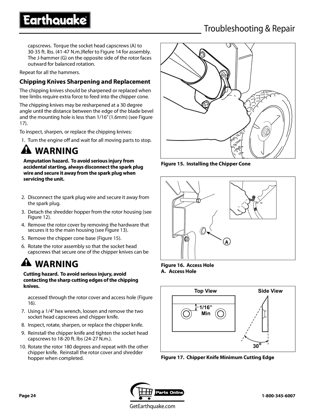
The chipping knives may be resharpened at a 30 degree angle until the distance between the edge of the blade bevel and the mounting hole is less than 1/16” (1.6mm) (see Figure 17).
To inspect, sharpen, or replace the chipping knives:
1.Turn the engine off and wait for all moving parts to stop.
![]() WARNING
WARNING
Amputation hazard. To avoid serious injury from accidental starting, always disconnect the spark plug wire and secure it away from the spark plug when servicing the unit.
2.Disconnect the spark plug wire and secure it away from the spark plug.
3.Detach the shredder hopper from the rotor housing (see Figure 12).
4.Remove the rotor cover by removing the hardware that secures it to the main housing (see Figure 13).
5.Remove the chipper cone base (Figure 15).
6.Rotate the rotor assembly so that the socket head capscrews that secure one of the chipper knives can be
![]() WARNING
WARNING
Cutting hazard. To avoid serious injury, avoid contacting the sharp cutting edges of the chipping knives.
accessed through the rotor cover and access hole (Figure 16).
7.Using a 1/4” hex wrench, loosen and remove the two socket head capscrews and chipper knife.
8.Inspect, rotate, sharpen, or replace the chipper knife.
9.Reinstall the chipper knife and tighten the socket head capscrews to
10. Rotate the rotor 180 degrees and repeat with the other chipper knife. Reinstall the rotor cover and shredder hopper when completed.
Troubleshooting & Repair
Figure 15. Installing the Chipper Cone
A |
Figure 16. Access Hole
A. Access Hole
Top View | Side View |
![]() 1/16”
1/16”
Min
30°
Figure 17. Chipper Knife Minimum Cutting Edge
Page 24
GetEarthquake.com