|
|
|
|
| NEMA Contactors & Starters | 19 | |
|
|
|
|
| |||
|
|
|
| ||||
September 2003 | IT. | ||||||
| |||||||
Dimensions |
| ||||||
|
|
|
|
|
| ||
|
| ||||||
|
| ||||||
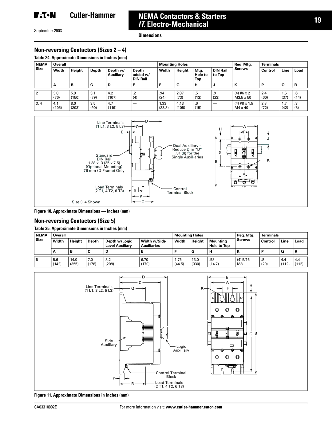
Table 24. Approximate Dimensions in Inches (mm) |
| ||||||
NEMA | Overall |
|
|
|
| Mounting Holes |
|
| Req. Mtg. | Terminals |
|
| ||
Size |
|
|
|
|
|
|
|
|
| Screws |
|
|
| |
Width | Height | Depth | Depth w/ | Depth | Width | Height | Mtg. | DIN Rail | Control | Line | Load | |||
|
| |||||||||||||
|
|
|
| Auxiliary | added w/ |
|
| Hole to | to Top |
|
|
|
| |
|
|
|
|
| DIN Rail |
|
| Top |
|
|
|
|
| |
|
|
|
|
|
|
|
|
|
|
|
|
|
| |
| A | B | C | D | E | F | G | H | J | K | P | Q | R | |
|
|
|
|
|
|
|
|
|
|
|
|
|
| |
|
|
|
|
|
|
|
|
|
|
|
|
|
| |
2 | 3.0 | 5.9 | 3.1 | 4.2 | .2 | .94 | 2.87 | .5 | .9 | (4) #6 x 2 | 2.4 | 1.5 | .6 | |
| (76) | (150) | (79) | (107) | (4) | (24) | (73) | (13) | (23) | M3.5 x 50 | (60) | (37) | (14) | |
|
|
|
|
|
|
|
|
|
|
|
|
|
| |
3, 4 | 4.1 | 8.0 | 3.5 | 4.7 | — | 1.33 | 4.13 | .6 | — | (4) #8 x 1.5 | 2.8 | 1.7 | .3 | |
| (105) | (203) | (90) | (119) |
| (33.8) | (105) | (15) |
| M4 x 40 | (72) | (42) | (8) | |
Line Terminals |
| D |
|
|
|
|
|
|
(1 L1, 3 L2, 5 L3) | Q |
| H |
|
| A |
|
|
E |
|
|
|
| F |
|
| |
|
|
|
|
|
|
| ||
|
|
|
|
|
|
|
| J |
|
| Dual Auxiliary – |
|
|
|
|
|
|
|
| Reduce Dim “D” | G |
|
|
|
|
|
Standard |
| .31 (8) for the |
|
|
|
|
| |
| Single Auxiliaries |
|
|
|
|
|
| |
DIN Rail |
|
|
|
|
|
| K | |
|
| B |
|
|
|
| ||
1.38 x .3 (35 x 7.5) |
|
|
|
|
|
| ||
|
|
|
|
|
|
| ||
(Optional Mounting) |
|
|
|
|
|
|
|
|
76 mm |
|
|
|
|
|
|
|
|
Load Terminals |
| Control | 2 | T1 | 4 | T2 | 6 | T3 |
|
|
|
|
|
|
| ||
(2 T1, 4 T2, 6 T3) | R |
|
|
|
|
|
| |
Terminal Block |
|
|
|
|
|
| ||
|
|
|
|
|
|
|
| |
|
| P |
|
|
|
|
|
|
Size 3, 4 Shown |
| C |
|
|
|
|
|
|
Figure 10. Approximate Dimensions — Inches (mm)
Non-reversing Contactors (Size 5)
Table 25. Approximate Dimensions in Inches (mm)
NEMA | Overall |
|
|
|
| Mounting Holes |
| Req. Mtg. | Terminals |
|
| ||
Size |
|
|
|
|
|
|
|
| Screws |
|
|
| |
Width | Height | Depth | Depth w/Logic | Width w/Side | Width | Height | Mounting | Control | Line | Load | |||
|
| ||||||||||||
|
|
|
| Level Auxiliary | Auxiliaries |
|
| Hole to Top |
|
|
|
| |
|
|
|
|
|
|
|
|
|
|
|
|
| |
| A | B | C | D | E | F | G | H | K | P | Q | R | |
|
|
|
|
|
|
|
|
|
|
|
|
| |
|
|
|
|
|
|
|
|
|
|
|
|
| |
5 | 5.6 | 14.0 | 7.0 | 8.2 | 6.70 | 1.75 | 13.0 | .58 | (4) 5/16 | .8 | 4.4 | 4.4 | |
| (142) | (355) | (178) | (208) | (170) | (44.5) | (330) | (14.7) | M8 | (20) | (112) | (112) | |
|
|
|
|
|
|
|
|
|
|
|
|
| |
| D |
| E |
| C |
| A |
Line Terminals | Q | K | H |
(1 L1, 3 L2, 5 L3) | F | ||
|
|
| |
|
|
| G B |
Side |
|
|
|
Auxiliary |
| Logic |
|
|
| Auxiliary |
|
|
| Control Terminal |
|
P |
| Block |
|
| Load Terminals |
| |
| R |
| |
|
| (2 T1, 4 T2, 6 T3) |
|
Figure 11. Approximate Dimensions in Inches (mm)
CA03310002E | For more information visit: |