22 | NEMA Contactors & Starters |
|
|
|
| |
|
|
|
| |||
|
|
|
| |||
IT. | ||||||
| ||||||
|
|
| September 2003 | |||
| Dimensions | |||||
|
|
|
|
|
| |
|
| |||||
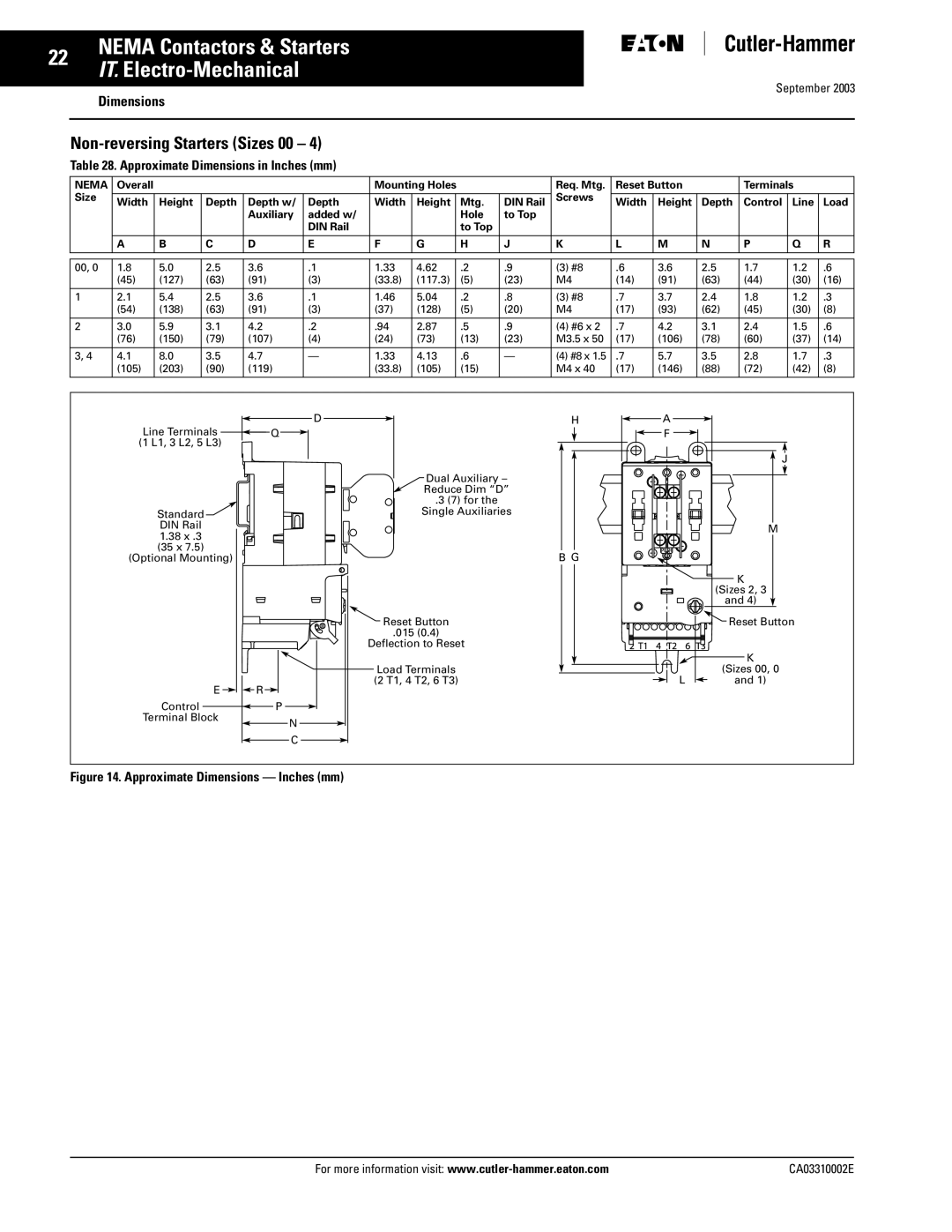
| Table 28. Approximate Dimensions in Inches (mm) | |||||
NEMA | Overall |
|
|
|
| Mounting Holes |
|
| Req. Mtg. | Reset Button |
| Terminals |
| ||||
Size |
|
|
|
|
|
|
|
|
|
| Screws |
|
|
|
|
|
|
Width | Height | Depth | Depth w/ | Depth | Width | Height |
| Mtg. | DIN Rail | Width | Height | Depth | Control | Line | Load | ||
|
|
|
| Auxiliary | added w/ |
|
|
| Hole | to Top |
|
|
|
|
|
|
|
|
|
|
|
| DIN Rail |
|
|
| to Top |
|
|
|
|
|
|
|
|
|
|
|
|
|
|
|
|
|
|
|
|
|
|
|
|
|
|
| A | B | C | D | E | F | G |
| H | J | K | L | M | N | P | Q | R |
|
|
|
|
|
|
|
|
|
|
|
|
|
|
|
|
|
|
|
|
|
|
|
|
|
|
|
|
|
|
|
|
|
|
|
|
00, 0 | 1.8 | 5.0 | 2.5 | 3.6 | .1 | 1.33 | 4.62 |
| .2 | .9 | (3) #8 | .6 | 3.6 | 2.5 | 1.7 | 1.2 | .6 |
| (45) | (127) | (63) | (91) | (3) | (33.8) | (117.3) |
| (5) | (23) | M4 | (14) | (91) | (63) | (44) | (30) | (16) |
|
|
|
|
|
|
|
|
|
|
|
|
|
|
|
|
|
|
1 | 2.1 | 5.4 | 2.5 | 3.6 | .1 | 1.46 | 5.04 |
| .2 | .8 | (3) #8 | .7 | 3.7 | 2.4 | 1.8 | 1.2 | .3 |
| (54) | (138) | (63) | (91) | (3) | (37) | (128) |
| (5) | (20) | M4 | (17) | (93) | (62) | (45) | (30) | (8) |
2 | 3.0 | 5.9 | 3.1 | 4.2 | .2 | .94 | 2.87 |
| .5 | .9 | (4) #6 x 2 | .7 | 4.2 | 3.1 | 2.4 | 1.5 | .6 |
| (76) | (150) | (79) | (107) | (4) | (24) | (73) |
| (13) | (23) | M3.5 x 50 | (17) | (106) | (78) | (60) | (37) | (14) |
|
|
|
|
|
|
|
|
|
|
|
|
|
|
|
|
|
|
3, 4 | 4.1 | 8.0 | 3.5 | 4.7 | — | 1.33 | 4.13 |
| .6 | — | (4) #8 x 1.5 | .7 | 5.7 | 3.5 | 2.8 | 1.7 | .3 |
| (105) | (203) | (90) | (119) |
| (33.8) | (105) |
| (15) |
| M4 x 40 | (17) | (146) | (88) | (72) | (42) | (8) |
|
|
|
|
|
|
|
|
|
|
|
|
|
|
|
|
|
|
Line Terminals ![]() Q
Q ![]() (1 L1, 3 L2, 5 L3)
(1 L1, 3 L2, 5 L3)
Standard![]()
DIN Rail
1.38x .3 (35 x 7.5)
(Optional Mounting)
| E |
|
|
|
| R |
|
|
|
|
|
| |
Control |
|
|
| P |
|
|
| ||||||
|
|
|
|
|
|
|
|
|
|
| |||
|
|
|
|
|
|
|
|
| |||||
Terminal Block |
|
|
|
|
|
|
| N | |||||
|
|
|
|
|
|
|
|
|
|
|
|
| |
|
|
|
|
|
|
|
|
|
|
|
|
| C |
|
|
|
|
|
|
|
|
|
|
|
|
| |
D | H | A |
|
|
| F |
|
|
|
| J |
| Dual Auxiliary – |
|
|
| Reduce Dim “D” |
|
|
| .3 (7) for the |
|
|
| Single Auxiliaries |
|
|
|
|
| M |
| B G |
|
|
|
|
| K |
|
|
| (Sizes 2, 3 |
|
|
| and 4) |
| Reset Button |
| Reset Button |
| .015 (0.4) |
|
|
| Deflection to Reset |
|
|
|
|
| K |
| Load Terminals |
| (Sizes 00, 0 |
| (2 T1, 4 T2, 6 T3) | L | and 1) |
Figure 14. Approximate Dimensions — Inches (mm)
For more information visit: | CA03310002E |