|
|
|
|
|
| NEMA Contactors & Starters | 11 | |
|
|
|
|
|
| |||
|
|
|
|
|
| |||
September 2003 | IT. | |||||||
| ||||||||
Technical Data and Specifications |
| |||||||
|
|
|
|
|
|
| ||
|
| |||||||
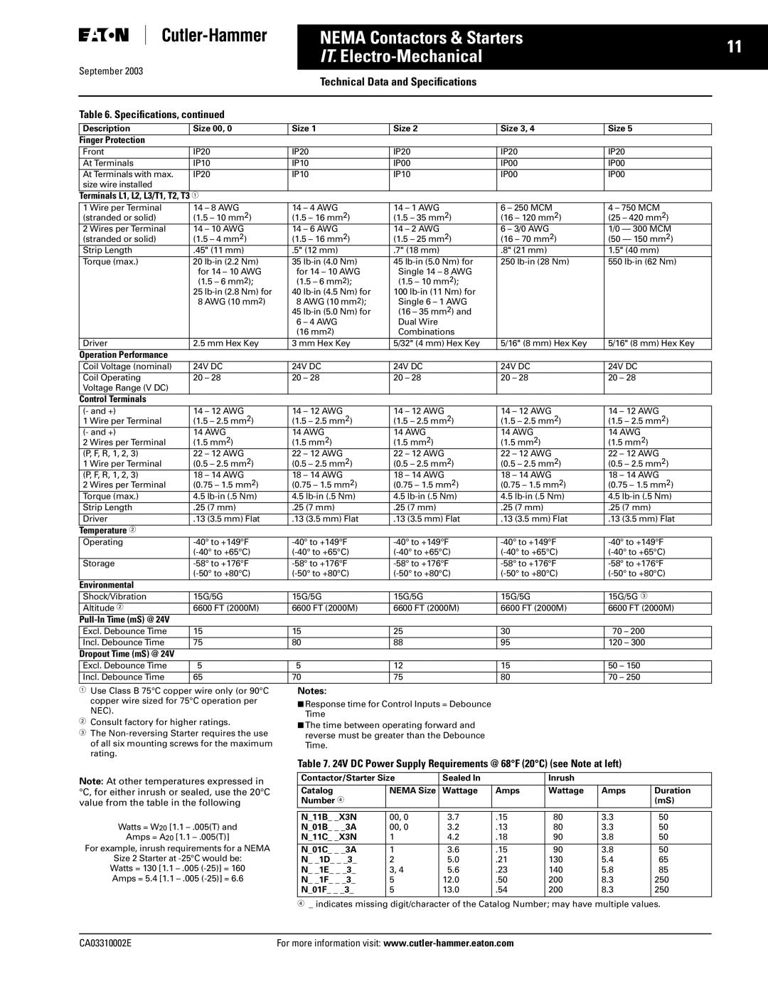
Table 6. Specifications, continued |
| |||||||
Description | Size 00, 0 | Size 1 | Size 2 | Size 3, 4 | Size 5 |
Finger Protection |
|
|
|
|
|
Front | IP20 | IP20 | IP20 | IP20 | IP20 |
At Terminals | IP10 | IP10 | IP00 | IP00 | IP00 |
At Terminals with max. | IP20 | IP10 | IP10 | IP00 | IP00 |
size wire installed |
|
|
|
|
|
Terminals L1, L2, L3/T1, T2, T3 |
|
|
|
|
|
1 Wire per Terminal | 14 – 8 AWG | 14 – 4 AWG | 14 – 1 AWG | 6 – 250 MCM | 4 – 750 MCM |
(stranded or solid) | (1.5 – 10 mm2) | (1.5 – 16 mm2) | (1.5 – 35 mm2) | (16 – 120 mm2) | (25 – 420 mm2) |
2 Wires per Terminal | 14 – 10 AWG | 14 – 6 AWG | 14 – 2 AWG | 6 – 3/0 AWG | 1/0 — 300 MCM |
(stranded or solid) | (1.5 – 4 mm2) | (1.5 – 16 mm2) | (1.5 – 25 mm2) | (16 – 70 mm2) | (50 — 150 mm2) |
Strip Length | .45" (11 mm) | .5" (12 mm) | .7" (18 mm) | .8" (21 mm) | 1.5" (40 mm) |
Torque (max.) | 20 | 35 | 45 | 250 | 550 |
| for 14 – 10 AWG | for 14 – 10 AWG | Single 14 – 8 AWG |
|
|
| (1.5 – 6 mm2); | (1.5 – 6 mm2); | (1.5 – 10 mm2); |
|
|
| 25 | 40 | 100 |
|
|
| 8 AWG (10 mm2) | 8 AWG (10 mm2); | Single 6 – 1 AWG |
|
|
|
| 45 | (16 – 35 mm2) and |
|
|
|
| 6 – 4 AWG | Dual Wire |
|
|
|
| (16 mm2) | Combinations |
|
|
Driver | 2.5 mm Hex Key | 3 mm Hex Key | 5/32" (4 mm) Hex Key | 5/16" (8 mm) Hex Key | 5/16" (8 mm) Hex Key |
Operation Performance |
|
|
|
|
|
Coil Voltage (nominal) | 24V DC | 24V DC | 24V DC | 24V DC | 24V DC |
Coil Operating | 20 – 28 | 20 – 28 | 20 – 28 | 20 – 28 | 20 – 28 |
Voltage Range (V DC) |
|
|
|
|
|
Control Terminals |
|
|
|
|
|
(- and +) | 14 – 12 AWG | 14 – 12 AWG | 14 – 12 AWG | 14 – 12 AWG | 14 – 12 AWG |
1 Wire per Terminal | (1.5 – 2.5 mm2) | (1.5 – 2.5 mm2) | (1.5 – 2.5 mm2) | (1.5 – 2.5 mm2) | (1.5 – 2.5 mm2) |
(- and +) | 14 AWG | 14 AWG | 14 AWG | 14 AWG | 14 AWG |
2 Wires per Terminal | (1.5 mm2) | (1.5 mm2) | (1.5 mm2) | (1.5 mm2) | (1.5 mm2) |
(P, F, R, 1, 2, 3) | 22 – 12 AWG | 22 – 12 AWG | 22 – 12 AWG | 22 – 12 AWG | 22 – 12 AWG |
1 Wire per Terminal | (0.5 – 2.5 mm2) | (0.5 – 2.5 mm2) | (0.5 – 2.5 mm2) | (0.5 – 2.5 mm2) | (0.5 – 2.5 mm2) |
(P, F, R, 1, 2, 3) | 18 – 14 AWG | 18 – 14 AWG | 18 – 14 AWG | 18 – 14 AWG | 18 – 14 AWG |
2 Wires per Terminal | (0.75 – 1.5 mm2) | (0.75 – 1.5 mm2) | (0.75 – 1.5 mm2) | (0.75 – 1.5 mm2) | (0.75 – 1.5 mm2) |
Torque (max.) | 4.5 | 4.5 | 4.5 | 4.5 | 4.5 |
Strip Length | .25 (7 mm) | .25 (7 mm) | .25 (7 mm) | .25 (7 mm) | .25 (7 mm) |
Driver | .13 (3.5 mm) Flat | .13 (3.5 mm) Flat | .13 (3.5 mm) Flat | .13 (3.5 mm) Flat | .13 (3.5 mm) Flat |
Temperature |
|
|
|
|
|
Operating | |||||
| |||||
Storage | |||||
| |||||
Environmental |
|
|
|
|
|
Shock/Vibration | 15G/5G | 15G/5G | 15G/5G | 15G/5G | 15G/5G |
Altitude | 6600 FT (2000M) | 6600 FT (2000M) | 6600 FT (2000M) | 6600 FT (2000M) | 6600 FT (2000M) |
|
|
|
|
|
|
Excl. Debounce Time | 15 | 15 | 25 | 30 | 70 – 200 |
Incl. Debounce Time | 75 | 80 | 88 | 95 | 120 – 300 |
Dropout Time (mS) @ 24V |
|
|
|
|
|
Excl. Debounce Time | 5 | 5 | 12 | 15 | 50 – 150 |
Incl. Debounce Time | 65 | 70 | 75 | 80 | 70 – 250 |
Use Class B 75°C copper wire only (or 90°C copper wire sized for 75°C operation per NEC).
Consult factory for higher ratings.
The
Notes:
■Response time for Control Inputs = Debounce Time
■The time between operating forward and reverse must be greater than the Debounce Time.
Note: At other temperatures expressed in °C, for either inrush or sealed, use the 20°C value from the table in the following
Watts = W20 [1.1
Amps = A20 [1.1
For example, inrush requirements for a NEMA
Size 2 Starter at
Table 7. 24V DC Power Supply Requirements @ 68°F (20°C) (see Note at left)
Contactor/Starter Size | Sealed In |
| Inrush |
|
| |
Catalog | NEMA Size | Wattage | Amps | Wattage | Amps | Duration |
Number |
|
|
|
|
| (mS) |
|
|
|
|
|
|
|
|
|
|
|
|
|
|
N_11B_ _X3N | 00, 0 | 3.7 | .15 | 80 | 3.3 | 50 |
N_01B_ _ _3A | 00, 0 | 3.2 | .13 | 80 | 3.3 | 50 |
N_11C_ _X3N | 1 | 4.2 | .18 | 90 | 3.8 | 50 |
N_01C_ _ _3A | 1 | 3.6 | .15 | 90 | 3.8 | 50 |
N_ _1D_ _ _3_ | 2 | 5.0 | .21 | 130 | 5.4 | 65 |
N_ _1E_ _ _3_ | 3, 4 | 5.6 | .23 | 140 | 5.8 | 85 |
N_ _1F_ _ _3_ | 5 | 12.0 | .50 | 200 | 8.3 | 250 |
N_01F_ _ _3_ | 5 | 13.0 | .54 | 200 | 8.3 | 250 |
_ indicates missing digit/character of the Catalog Number; may have multiple values.
CA03310002E | For more information visit: |