Manuals
/
Cisco Systems
/
Computer Equipment
/
Computer Hardware
Cisco Systems
AVS 3120
installation instructions
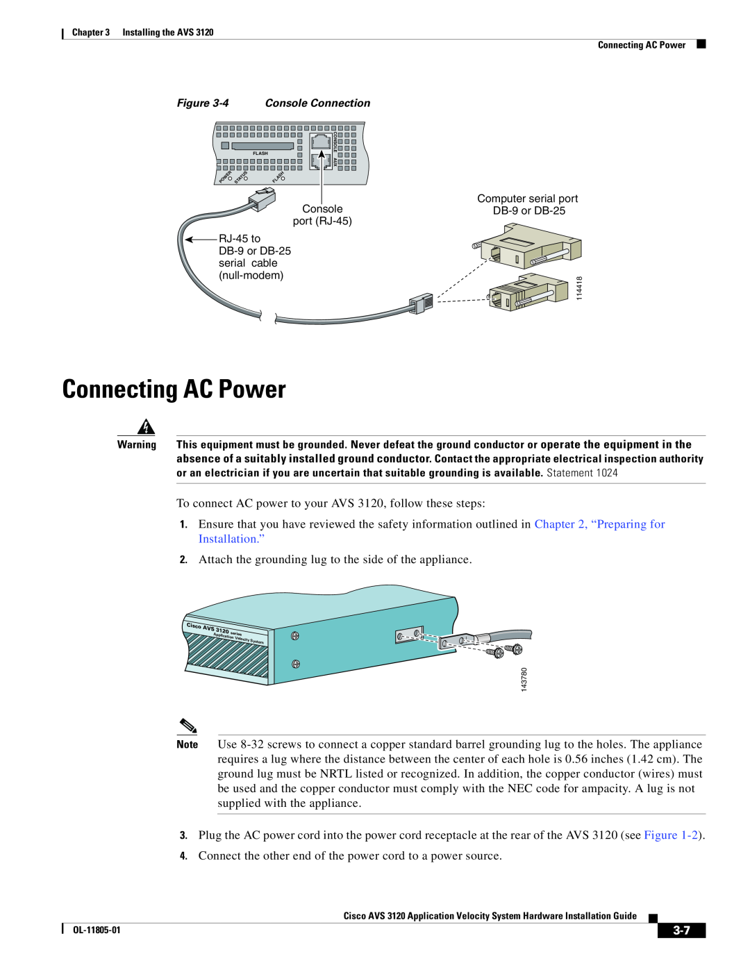
Connecting AC Power
Models:
AVS 3120
1
7
14
14
Download
14 pages
15.2 Kb
4
5
6
7
8
9
10
11
Install
Indicator
Connecting Cables
Configuring Network Settings
Connecting AC Power
Booting the AVS
Page 7
Image 7
Page 6
Page 8
Page 7
Image 7
Page 6
Page 8
Contents
Unpacking and Inspecting the AVS 3120, page
Installing Your AVS 3120, page Connecting Cables, page
Connecting AC Power, page Booting the AVS 3120, page
Configuring Network Settings, page Setting the Time, page
Unpacking and Inspecting the AVS
Installing Your AVS
If the Product is Damaged
Attaching a Two-Post Rack Bracket to the AVS
Installing the AVS 3120 on a Workbench or Tabletop
Attaching a Two-Post Rack Bracket to the AVS
3120
Figure 3-1 Attaching the Brackets to the Sides of the AVS
Installing the AVS 3120 on a Workbench or Tabletop
Connecting Cables
Connecting AC Power
Booting with a Console Connected
Booting the AVS
Establishing a Serial Console Connection
3-10
Configuring Network Settings
velocityshow timezone current
3-11
velocityshow dns
velocityset date tz timezone
3-12
Setting the Time
State
Indicator
Checking the Front Panel LEDs
Color
3-14
Removing or Replacing an AVS
Top
Page
Image
Contents