XT-40 & IT-RSS Installation | IM01005012E |
| |
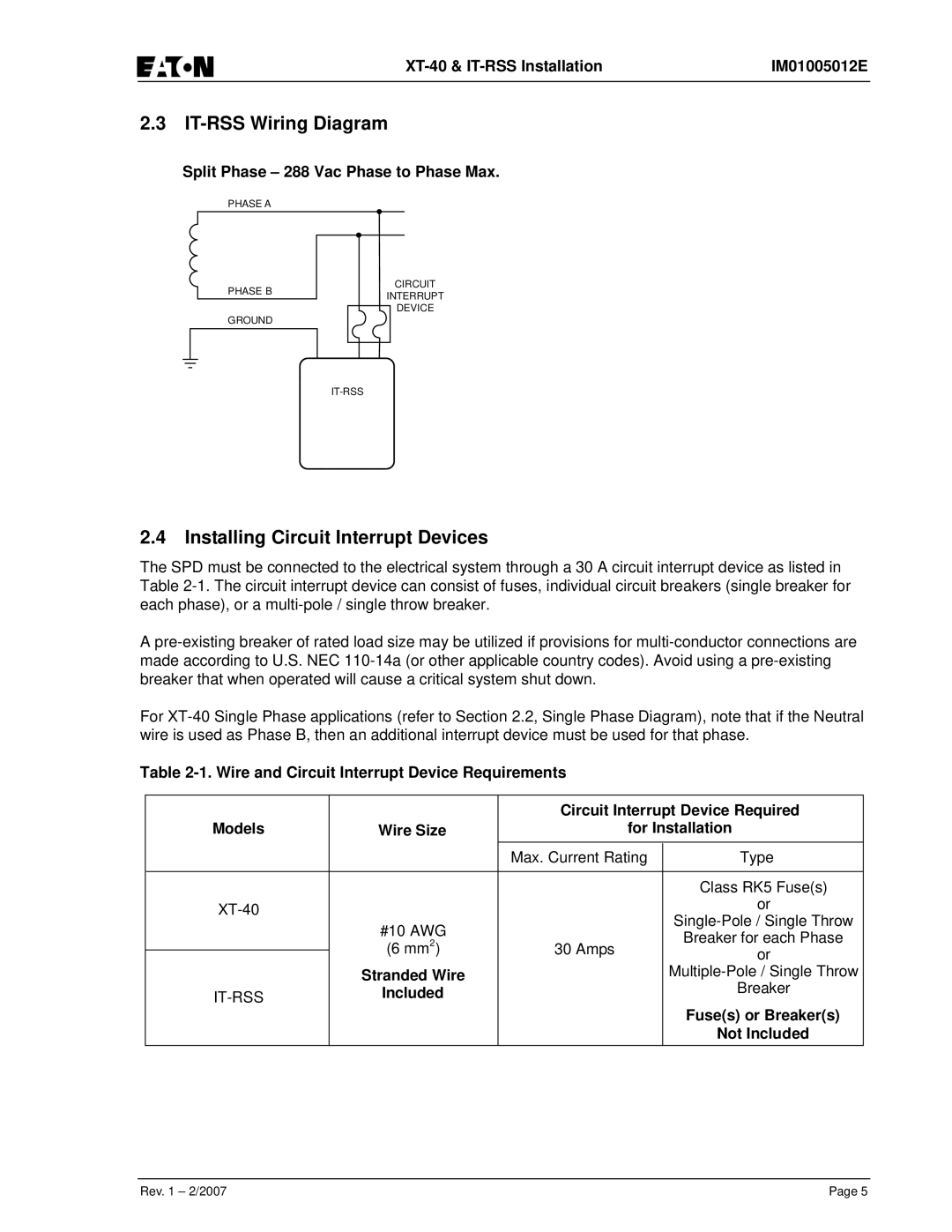
2.3IT-RSS Wiring Diagram
Split Phase – 288 Vac Phase to Phase Max.
PHASE A
CIRCUIT
PHASE BINTERRUPT
DEVICE
GROUND
IT-RSS
2.4Installing Circuit Interrupt Devices
The SPD must be connected to the electrical system through a 30 A circuit interrupt device as listed in Table 2-1. The circuit interrupt device can consist of fuses, individual circuit breakers (single breaker for each phase), or a multi-pole / single throw breaker.
A pre-existing breaker of rated load size may be utilized if provisions for multi-conductor connections are made according to U.S. NEC 110-14a (or other applicable country codes). Avoid using a pre-existing breaker that when operated will cause a critical system shut down.
For XT-40 Single Phase applications (refer to Section 2.2, Single Phase Diagram), note that if the Neutral wire is used as Phase B, then an additional interrupt device must be used for that phase.
Table 2-1. Wire and Circuit Interrupt Device Requirements
| | | Circuit Interrupt Device Required |
Models | Wire Size | for Installation |
| | | Max. Current Rating | Type |
| | | | |
| | | | Class RK5 Fuse(s) |
XT-40 | | | | or |
| | | Single-Pole / Single Throw |
| #10 AWG | |
| | Breaker for each Phase |
| 2 | | |
| (6 mm | ) | 30 Amps | or |
|
| Stranded Wire | | Multiple-Pole / Single Throw |
IT-RSS | Included | | Breaker |
| | | | Fuse(s) or Breaker(s) |
| | | | Not Included |