IM01005012E | |
|
|
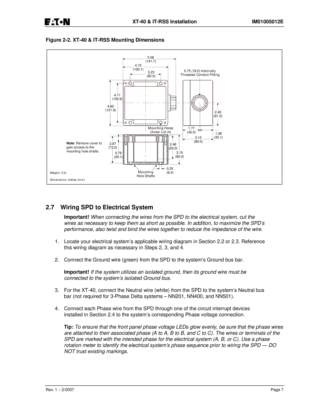
Figure 2-2. XT-40 & IT-RSS Mounting Dimensions
|
| 5.58 |
|
|
|
|
| (141.7) |
|
|
|
|
| 4.73 |
|
|
|
|
| (120.1) |
| 0.75 (19.0) Internally | |
|
| 3.23 |
| ||
|
| Threaded Conduit Fitting | |||
|
| (82.0) | |||
|
|
|
|
| |
| 4.17 |
|
|
|
|
| (105.9) |
|
|
|
|
| 4.80 |
|
|
|
|
| (121.9) |
|
|
| 2.40 |
|
|
|
|
| |
|
|
|
|
| (61.0) |
|
| Mounting Holes | 1.77 |
| |
|
| Under Lid (4) | (45.0) | 1.38 | |
|
|
|
| 3.15 | (35.1) |
Note: Remove cover to | 2.87 |
| 2.48 | (80.0) |
|
|
|
| |||
gain access to the | (73.0) |
| (63.0) |
|
|
mounting hole shafts. | 0.79 |
| 3.15 |
|
|
| (20.1) |
| (80.0) |
|
|
|
|
|
|
|
|
|
|
|
|
|
|
|
|
|
|
|
|
|
|
|
|
|
|
|
|
|
|
|
|
|
|
| 0.25 |
| |
|
|
|
|
|
| Mounting |
| ||||||||||
|
|
|
|
|
|
|
| ||||||||||
Weight: 3 lb |
|
|
| (6.4) |
| ||||||||||||
|
|
|
|
|
| Hole Shafts |
|
|
|
|
|
|
|
|
|
| |
Dimensions: Inches (mm)
2.7Wiring SPD to Electrical System
Important! When connecting the wires from the SPD to the electrical system, cut the wires as necessary to keep them as short as possible. In addition, to maximize the SPD’s performance, also twist and bind the wires together to reduce the impedance of the wire.
1.Locate your electrical system’s applicable wiring diagram in Section 2.2 or 2.3. Reference this wiring diagram as necessary in Steps 2, 3, and 4.
2.Connect the Ground wire (green) from the SPD to the system’s Ground bus bar.
Important! If the system utilizes an isolated ground, then its ground wire must be connected to the system’s isolated Ground bus.
3.For the
4.Connect each Phase wire from the SPD through one of the circuit interrupt devices installed in Section 2.4 to the system’s corresponding Phase voltage connection.
Tip: To ensure that the front panel phase voltage LEDs glow evenly, be sure that the phase wires are attached to their associated phase (A to A, B to B, and C to C). The wires or terminals of the SPD are marked with the intended phase for the electrical system (A, B, or C). Use a phase rotation meter to identify the electrical system’s phase sequence prior to wiring the SPD — DO NOT trust existing markings.
Rev. 1 – 2/2007 | Page 7 |