IM01005012E | |
|
|
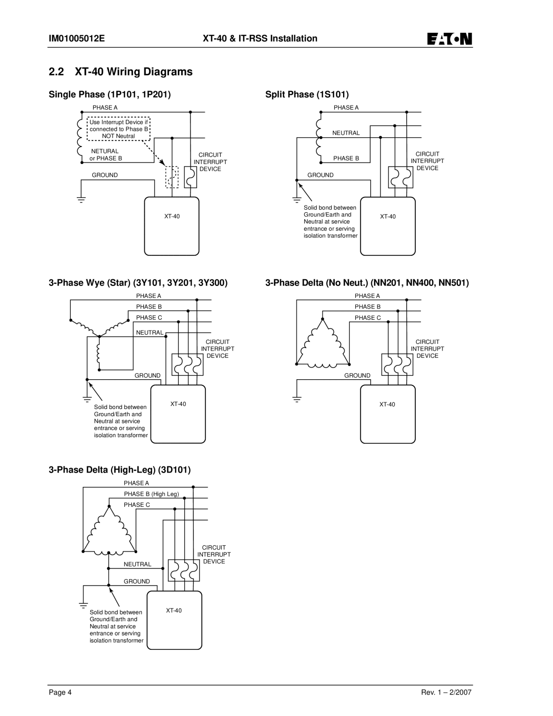
2.2XT-40 Wiring Diagrams
Single Phase (1P101, 1P201) | Split Phase (1S101) |
PHASE A
Use Interrupt Device if connected to Phase B NOT Neutral
NETURAL or PHASE B
GROUND
CIRCUIT
INTERRUPT
DEVICE
PHASE A
NEUTRAL
PHASE B | CIRCUIT | |
INTERRUPT | ||
| ||
GROUND | DEVICE | |
|
Solid bond between
Ground/Earth and
entrance or serving isolation transformer
PHASE A |
| PHASE A |
PHASE B |
| PHASE B |
PHASE C |
| PHASE C |
NEUTRAL |
|
|
| CIRCUIT | CIRCUIT |
| INTERRUPT | INTERRUPT |
| DEVICE | DEVICE |
GROUND |
| GROUND |
Solid bond between | ||
|
| |
Ground/Earth and Neutral at service entrance or serving isolation transformer
3-Phase Delta (High-Leg) (3D101)
PHASE A
PHASE B (High Leg)
PHASE C
NEUTRAL
GROUND
Solid bond between Ground/Earth and Neutral at service entrance or serving isolation transformer
CIRCUIT
INTERRUPT
DEVICE
Page 4 | Rev. 1 – 2/2007 |