INSTALLATION
Multiple KVM Switches—Installation (Daisy-Chaining)
You can
When
Note: A
All ENTERPRISE
•For a
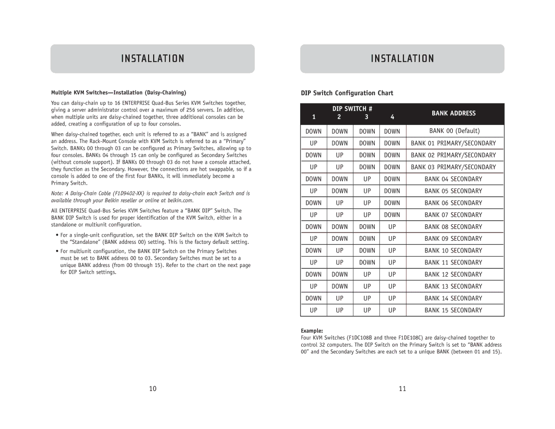
•For multiunit configuration, the BANK DIP Switch on the Primary Switches must be set to BANK address 00 to 03. Secondary Switches must be set to a unique BANK address (from 00 through 15). Refer to the chart on the next page for DIP Switch settings.
INSTALLATION
DIP Switch Configuration Chart
| DIP SWITCH # |
| BANK ADDRESS | ||
1 | 2 | 3 | 4 | ||
| |||||
|
|
|
|
| |
DOWN | DOWN | DOWN | DOWN | BANK 00 (Default) | |
|
|
|
|
| |
UP | DOWN | DOWN | DOWN | BANK 01 PRIMARY/SECONDARY | |
|
|
|
|
| |
DOWN | UP | DOWN | DOWN | BANK 02 PRIMARY/SECONDARY | |
|
|
|
|
| |
UP | UP | DOWN | DOWN | BANK 03 PRIMARY/SECONDARY | |
|
|
|
|
| |
DOWN | DOWN | UP | DOWN | BANK 04 SECONDARY | |
|
|
|
|
| |
UP | DOWN | UP | DOWN | BANK 05 SECONDARY | |
|
|
|
|
| |
DOWN | UP | UP | DOWN | BANK 06 SECONDARY | |
|
|
|
|
| |
UP | UP | UP | DOWN | BANK 07 SECONDARY | |
|
|
|
|
| |
DOWN | DOWN | DOWN | UP | BANK 08 SECONDARY | |
|
|
|
|
| |
UP | DOWN | DOWN | UP | BANK 09 SECONDARY | |
|
|
|
|
| |
DOWN | UP | DOWN | UP | BANK 10 SECONDARY | |
|
|
|
|
| |
UP | UP | DOWN | UP | BANK 11 SECONDARY | |
|
|
|
|
| |
DOWN | DOWN | UP | UP | BANK 12 SECONDARY | |
|
|
|
|
| |
UP | DOWN | UP | UP | BANK 13 SECONDARY | |
|
|
|
|
| |
DOWN | UP | UP | UP | BANK 14 SECONDARY | |
|
|
|
|
| |
UP | UP | UP | UP | BANK 15 SECONDARY | |
|
|
|
|
| |
Example:
Four KVM Switches (F1DC108B and three F1DE108C) are
10 | 11 |