Belkin F1DC108B Installation Before you begin, Adding Additional Units, Cautions and Warnings

Models: F1DC108B

1 15
Download 15 pages 42.2 Kb
Page 8
Image 8
Installation

INSTALLATION

Installation

Before you begin:

1.Make sure that all computers and Switches are powered off and that each Switch has been assigned a unique BANK address.

2.Place all Primary and Secondary Switches in the desired location.

3.Connect the servers to the Switch as previously described for a standalone configuration.
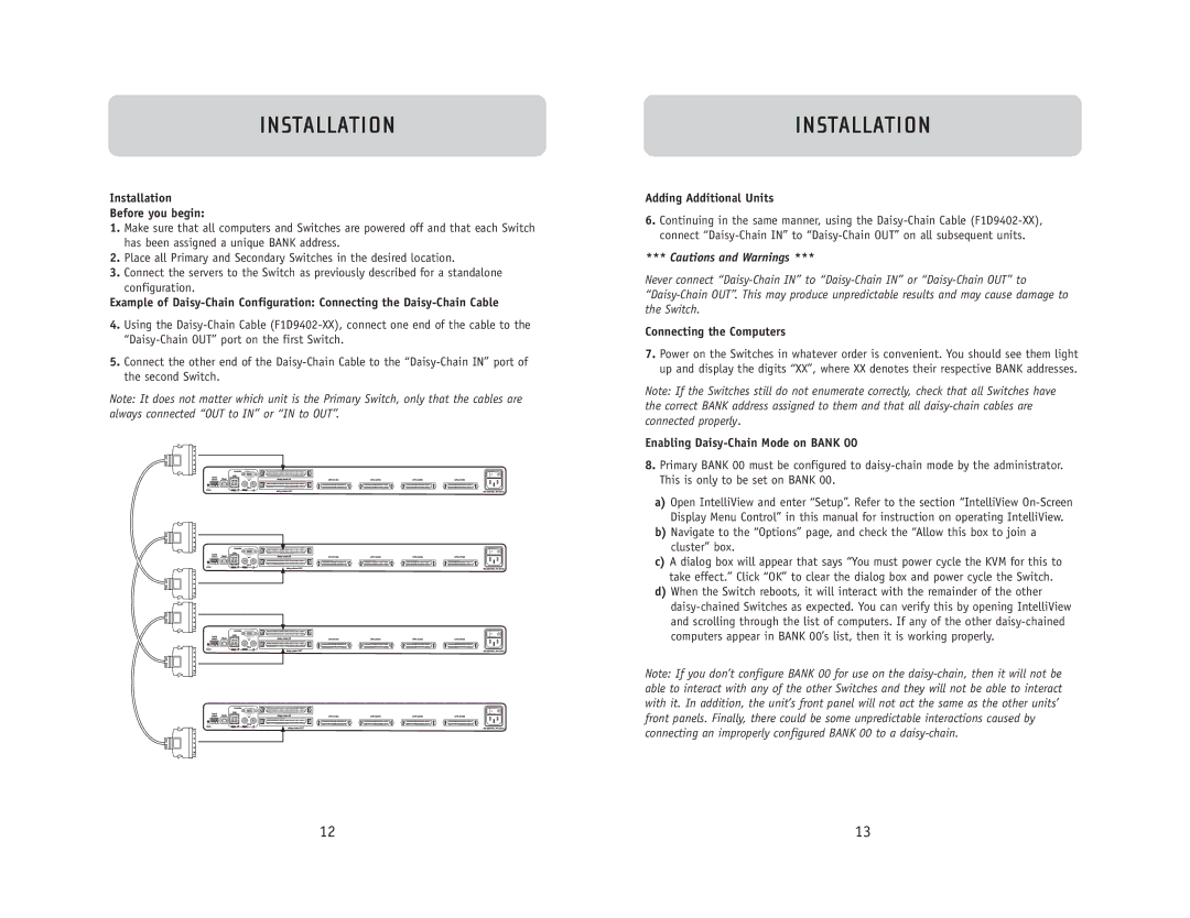
Example of Daisy-Chain Configuration: Connecting the Daisy-Chain Cable

4.Using the Daisy-Chain Cable (F1D9402-XX), connect one end of the cable to the “Daisy-Chain OUT” port on the first Switch.

5.Connect the other end of the Daisy-Chain Cable to the “Daisy-Chain IN” port of the second Switch.

Note: It does not matter which unit is the Primary Switch, only that the cables are always connected “OUT to IN” or “IN to OUT”.

INSTALLATION

Adding Additional Units

6.Continuing in the same manner, using the Daisy-Chain Cable (F1D9402-XX), connect “Daisy-Chain IN” to “Daisy-Chain OUT” on all subsequent units.

*** Cautions and Warnings ***

Never connect “Daisy-Chain IN” to “Daisy-Chain IN” or “Daisy-Chain OUT” to “Daisy-Chain OUT”. This may produce unpredictable results and may cause damage to the Switch.

Connecting the Computers

7.Power on the Switches in whatever order is convenient. You should see them light up and display the digits “XX”, where XX denotes their respective BANK addresses.

Note: If the Switches still do not enumerate correctly, check that all Switches have the correct BANK address assigned to them and that all daisy-chain cables are connected properly.

Enabling Daisy-Chain Mode on BANK 00

8.Primary BANK 00 must be configured to daisy-chain mode by the administrator. This is only to be set on BANK 00.

a)Open IntelliView and enter “Setup”. Refer to the section “IntelliView On-Screen Display Menu Control” in this manual for instruction on operating IntelliView.

b)Navigate to the “Options” page, and check the “Allow this box to join a cluster” box.

c)A dialog box will appear that says “You must power cycle the KVM for this to take effect.” Click “OK” to clear the dialog box and power cycle the Switch.

d)When the Switch reboots, it will interact with the remainder of the other daisy-chained Switches as expected. You can verify this by opening IntelliView and scrolling through the list of computers. If any of the other daisy-chained computers appear in BANK 00’s list, then it is working properly.

Note: If you don’t configure BANK 00 for use on the daisy-chain, then it will not be able to interact with any of the other Switches and they will not be able to interact with it. In addition, the unit’s front panel will not act the same as the other units’ front panels. Finally, there could be some unpredictable interactions caused by connecting an improperly configured BANK 00 to a daisy-chain.

12

13

Page 8
Image 8
Belkin F1DC108B Installation Before you begin, Example of Daisy-Chain Configuration Connecting the Daisy-Chain Cable