13 16
13 16
PRIORITY CONNECTORS
When a signal above –20 dB is detected at the priority input, the main input is muted. This is useful for making announcements, as the music program is then automatically muted. This muting can also be accomplished manually by connecting a user-supplied, normally open, dry contact closure switch to the priority screw terminals.
The Priority input has four different styles of input connections for microphone-level or line-level audio signals. Choose one which suits your system the best:
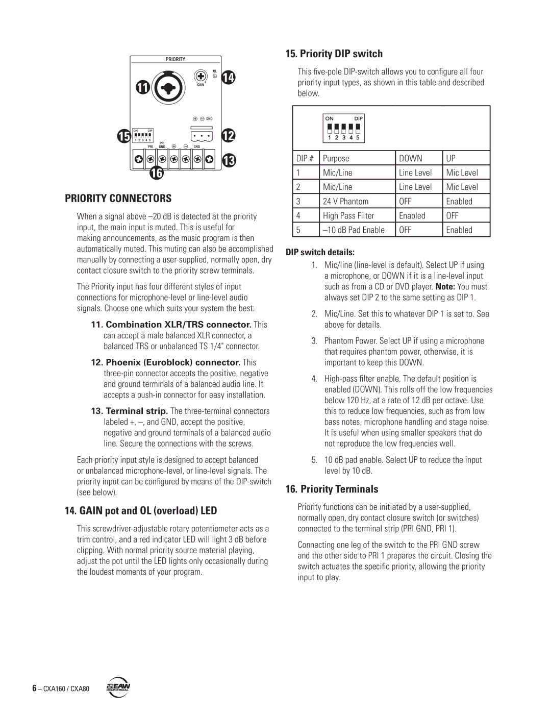
11.Combination XLR/TRS connector. This can accept a male balanced XLR connector, a balanced TRS or unbalanced TS 1/4" connector.
12.Phoenix (Euroblock) connector. This three-pin connector accepts the positive, negative and ground terminals of a balanced audio line. It accepts a push-in connector for easy installation.
13.Terminal strip. The three-terminal connectors labeled +, –, and GND, accept the positive, negative and ground terminals of a balanced audio line. Secure the connections with the screws.
Each priority input style is designed to accept balanced or unbalanced microphone-level, or line-level signals. The priority input can be configured by means of the DIP-switch (see below).
14. GAIN pot and OL (overload) LED
This screwdriver-adjustable rotary potentiometer acts as a trim control, and a red indicator LED will light 3 dB before clipping. With normal priority source material playing, adjust the pot until the LED lights only occasionally during the loudest moments of your program.
15. Priority DIP switch
This five-pole DIP-switch allows you to configure all four priority input types, as shown in this table and described below.
DIP # | Purpose | DOWN | UP |
1 | Mic/Line | Line Level | Mic Level |
2 | Mic/Line | Line Level | Mic Level |
3 | 24 V Phantom | OFF | Enabled |
4 | High Pass Filter | Enabled | OFF |
5 | –10 dB Pad Enable | OFF | Enabled |
DIP switch details:
1.Mic/line (line-level is default). Select UP if using a microphone, or DOWN if it is a line-level input such as from a CD or DVD player. Note: You must always set DIP 2 to the same setting as DIP 1.
2.Mic/Line. Set this to whatever DIP 1 is set to. See above for details.
3.Phantom Power. Select UP if using a microphone that requires phantom power, otherwise, it is important to keep this DOWN.
4.High-pass filter enable. The default position is enabled (DOWN). This rolls off the low frequencies below 120 Hz, at a rate of 12 dB per octave. Use this to reduce low frequencies, such as from low bass notes, microphone handling and stage noise. It is useful when using smaller speakers that do not reproduce the low frequencies well.
5.10 dB pad enable. Select UP to reduce the input level by 10 dB.
16.Priority Terminals
Priority functions can be initiated by a user-supplied, normally open, dry contact closure switch (or switches) connected to the terminal strip (PRI GND, PRI 1).
Connecting one leg of the switch to the PRI GND screw and the other side to PRI 1 prepares the circuit. Closing the switch actuates the specific priority, allowing the priority input to play.