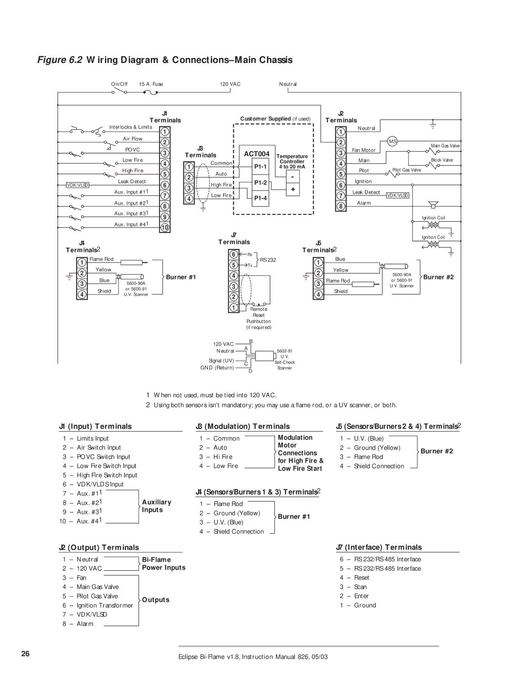
Figure 6.2 Wiring Diagram & Connections–Main Chassis


On/Off

15 A. Fuse


120 VAC

Neutral


J1


Customer Supplied (if used)

J2


Terminals


Terminals


Interlocks & Limits

1


1

Neutral


Air Flow

2


2


MS


J3


Main Gas Valve


POVC


Fan Motor


3


ACT004


3


Low Fire

Terminals

Temperature

Main


Block Valve


4

1

Common

P1-1

Controller

4


High Fire

4 to 20 mA

Pilot

Pilot Gas Valve


5


5


2

Auto


-


Leak Detect


P1-2

Ignition


VDK/VLSD


6

3

High Fire

+

6


Aux. Input #11


7

Low Fire


7

Leak Detect

VDK/VLSD


4

P1-4


Aux. Input #21


8


8

Alarm


Aux. Input #31


9


Ignition Coil


Aux. Input #41


10


J7


Ignition Coil

J4


Terminals

J5


Terminals2


6

Rx

Terminals2


Flame Rod


Blue


1


5

RS 232

1


Yellow


Tx


Yellow


2


4


2


5600-90A


Blue


Burner #1


Burner #2

3

5600-90A


3

Flame Rod


or 5600-91


3


U.V. Scanner


4

Shield

or 5600-91


4

Shield


U.V. Scanner


2


1

Remote


Reset


Pushbutton


(if required)


120 VAC


B

A


Neutral


Signal (UV)


GND (Return)

C


D


5602-91 U.V. Self-Check

Scanner

1When not used, must be tied into 120 VAC.

2Using both sensors isn’t mandatory; you may use a flame rod, or a UV scanner, or both.

J1 (Input) Terminals

J3 (Modulation) Terminals

J5 (Sensors/Burners 2 & 4) Terminals2

1

Limits Input


1

Common

Modulation


1

U.V. (Blue)


2

Air Switch Input

2

Auto

Motor

2

Ground (Yellow)

Burner #2

Connections

3

– POVC Switch Input

3

– Hi Fire

3

Flame Rod

for High Fire &


4

Low Fire Switch Input

4

Low Fire

4

Shield Connection


Low Fire Start


5– High Fire Switch Input

6– VDK/VLDS Input

7


1


J4 (Sensors/Burners 1 & 3) Terminals2

– Aux. #1


8

– Aux. #21

Auxiliary

1

– Flame Rod


9

Aux. #31

Inputs

2

Ground (Yellow)

Burner #1

10

Aux. #41


3

U.V. (Blue)


4

Shield Connection


J2 (Output) Terminals


J7 (Interface) Terminals

1

Neutral

Bi-Flame

6

RS 232/RS 485 Interface

2

– 120 VAC

Power Inputs

5

RS 232/RS 485 Interface

3

Fan


4

Reset

4

Main Gas Valve


3

Scan

5

Pilot Gas Valve

Outputs

2

Enter

6

Ignition Transformer

1

– Ground


7

– VDK/VLSD


8

– Alarm


26

Eclipse Bi-Flame v1.8, Instruction Manual 826, 05/03


Page 26
Image 26
Eclipse Combustion 6500 instruction manual Wiring Diagram & Connections-Main Chassis

6500 specifications

The Eclipse Combustion 6500 is a cutting-edge industrial burner designed to optimize combustion efficiency and reduce emissions in various applications. Known for its innovative approach to fuel burning, the 6500 model combines advanced technology with robust engineering, making it a preferred choice for industries such as power generation, manufacturing, and petrochemicals.

One of the hallmark features of the Eclipse Combustion 6500 is its versatility to operate on multiple fuels, including natural gas, propane, and biogas. This flexibility allows companies to adapt to changing fuel availability and cost, ensuring operational efficiency and economic viability. The burner is designed with a range of firing rates, catering to both small and large-scale applications, which enhances its utility across diverse operational scenarios.

Another significant characteristic of the 6500 is its sophisticated control system. The burner employs advanced digital controls that enable precision in fuel-to-air ratios and overall combustion management. This technology not only optimizes thermal performance but also facilitates compliance with stringent emissions regulations. By continuously monitoring combustion conditions, the 6500 ensures maximum efficiency while minimizing harmful emissions of nitrogen oxides (NOx) and carbon monoxide (CO).

Moreover, the Eclipse Combustion 6500 features a unique combustion geometry. This design promotes a stable flame while maintaining excellent mixing of fuel and air. The result is improved combustion efficiency and a reduction in pollutant formation. The structural integrity of the burner is engineered to handle high temperatures and corrosive environments, ensuring long-term reliability and reduced maintenance needs.

Safety is a paramount consideration in the design of the 6500. Integrated safety systems monitor operational parameters and provide alerts to prevent unsafe conditions. This focus on safety, combined with high performance, ensures that the burner not only meets but exceeds industry standards.

In summary, the Eclipse Combustion 6500 stands out due to its versatility, advanced control technologies, and efficient combustion capabilities. Its design prioritizes safety, reliability, and compliance with environmental regulations, making it an ideal choice for various industrial applications. As industries strive for greener and more efficient operations, the 6500 is poised to play a pivotal role in the evolution of combustion technology.