7 | 8 |
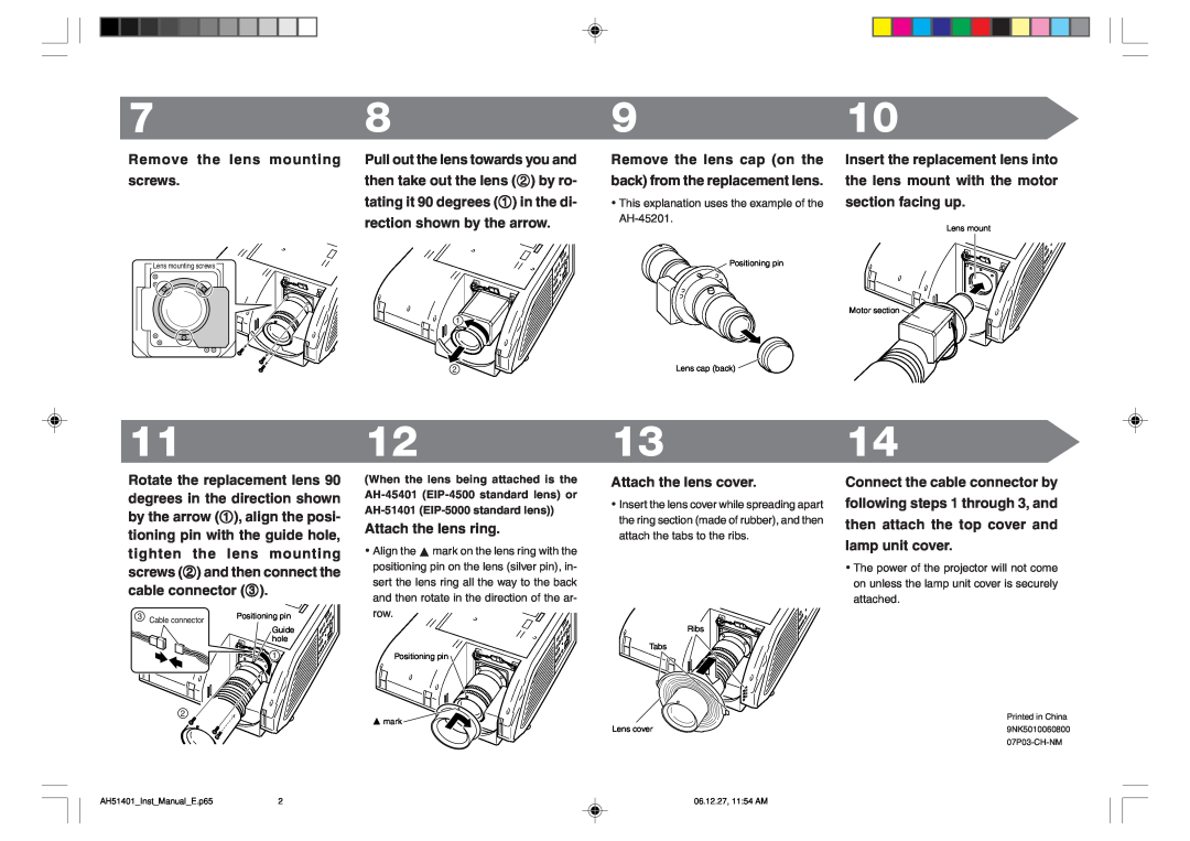
Remove the lens mounting | Pull out the lens towards you and |
screws. | then take out the lens (2) by ro- |
| tating it 90 degrees (1) in the di- |
| rection shown by the arrow. |
Lens mounting screws |
|
| 1 |
| 2 |
9
Remove the lens cap (on the back) from the replacement lens.
•This explanation uses the example of the
![]() Positioning pin
Positioning pin
Lens cap (back) ![]()
10
Insert the replacement lens into the lens mount with the motor section facing up.
Lens mount
Motor section ![]()
11
Rotate the replacement lens 90 degrees in the direction shown by the arrow (1), align the posi- tioning pin with the guide hole, tighten the lens mounting screws (2) and then connect the cable connector (3).
3 Cable connector | Positioning pin |
Guide hole
1 |
2
12
(When the lens being attached is the
Attach the lens ring.
•Align the a mark on the lens ring with the positioning pin on the lens (silver pin), in- sert the lens ring all the way to the back and then rotate in the direction of the ar- row. ![]()
Positioning pin
a mark ![]()
13
Attach the lens cover.
•Insert the lens cover while spreading apart the ring section (made of rubber), and then attach the tabs to the ribs.
Ribs
Tabs
Lens cover
14
Connect the cable connector by following steps 1 through 3, and then attach the top cover and lamp unit cover.
•The power of the projector will not come on unless the lamp unit cover is securely attached.
Printed in China
9NK5010060800
AH51401_Inst_Manual_E.p65 | 2 | 06.12.27, 11:54 AM |