CONTRACTOR PRECISION SERIES
HIGH | LOW | Address | ||
0 |
| 0 | ||
|
|
|
|
|
0 | 1... | F | 1... | 15 |
|
|
|
|
|
1 | 0... | F | 16... | 31 |
|
|
|
|
|
2 | 0... | F | 32... | 47 |
|
|
|
|
|
3 | 0... | F | 48... | 63 |
|
|
|
|
|
4 | 0... | F | 64... | 79 |
|
|
|
|
|
5 | 0... | F | 80... | 95 |
|
|
|
|
|
6 | 0... | F | 96... | 111 |
|
|
|
|
|
7 | 0... | F | 112... | 127 |
|
|
|
|
|
HIGH | LOW | Address | ||
8 | 0... | F | 128... | 143 |
|
|
|
|
|
9 | 0... | F | 144... | 159 |
|
|
|
|
|
A | 0... | F | 160... | 175 |
|
|
|
|
|
B | 0... | F | 176... | 191 |
|
|
|
|
|
C | 0... | F | 192... | 207 |
|
|
|
|
|
D | 0... | F | 208... | 223 |
|
|
|
|
|
E | 0... | F | 224... | 239 |
|
|
|
|
|
F | 0... | A | 240... | 250 |
|
|
|
| |
F | B... | F | reserved | |
|
|
|
|
|
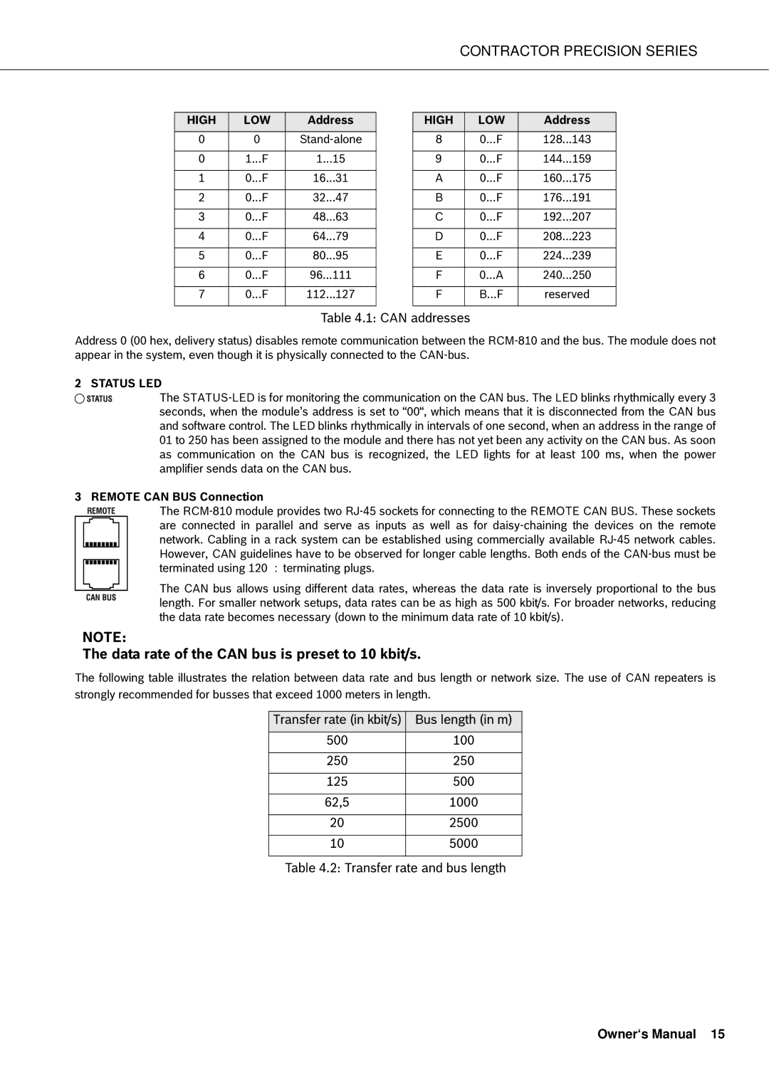
Table 4.1: CAN addresses
Address 0 (00 hex, delivery status) disables remote communication between the
2 STATUS LED
The
3 REMOTE CAN BUS Connection
The
The CAN bus allows using different data rates, whereas the data rate is inversely proportional to the bus length. For smaller network setups, data rates can be as high as 500 kbit/s. For broader networks, reducing the data rate becomes necessary (down to the minimum data rate of 10 kbit/s).
NOTE:
The data rate of the CAN bus is preset to 10 kbit/s.
The following table illustrates the relation between data rate and bus length or network size. The use of CAN repeaters is strongly recommended for busses that exceed 1000 meters in length.
Transfer rate (in kbit/s) | Bus length (in m) |
500 | 100 |
|
|
250 | 250 |
|
|
125 | 500 |
|
|
62,5 | 1000 |
|
|
20 | 2500 |
|
|
10 | 5000 |
|
|
Table 4.2: Transfer rate and bus length