CONTRACTOR PRECISION SERIES
2 Installation
2.1 Controls, Indicators and Connections
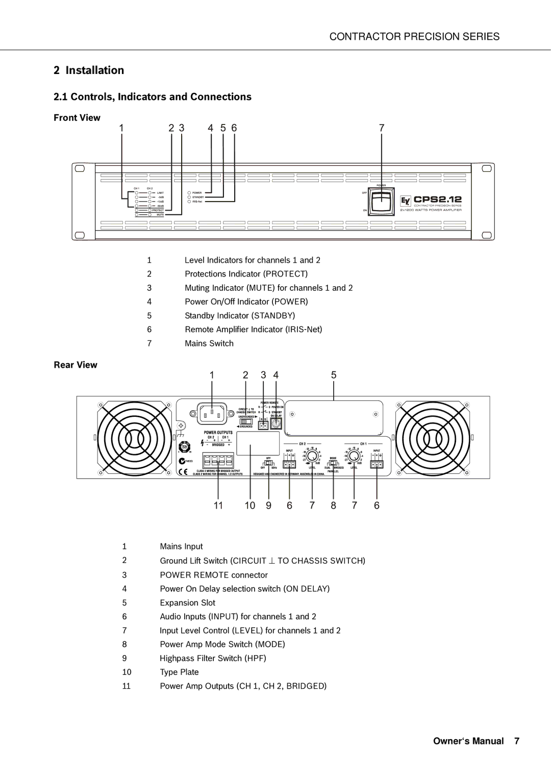
Front View
1Level Indicators for channels 1 and 2
2Protections Indicator (PROTECT)
3Muting Indicator (MUTE) for channels 1 and 2
4Power On/Off Indicator (POWER)
5Standby Indicator (STANDBY)
6Remote Amplifier Indicator
7Mains Switch
Rear View
1Mains Input
2Ground Lift Switch (CIRCUIT ⊥ TO CHASSIS SWITCH)
3POWER REMOTE connector
4Power On Delay selection switch (ON DELAY)
5Expansion Slot
6Audio Inputs (INPUT) for channels 1 and 2
7Input Level Control (LEVEL) for channels 1 and 2
8Power Amp Mode Switch (MODE)
9Highpass Filter Switch (HPF)
10 Type Plate
11 Power Amp Outputs (CH 1, CH 2, BRIDGED)