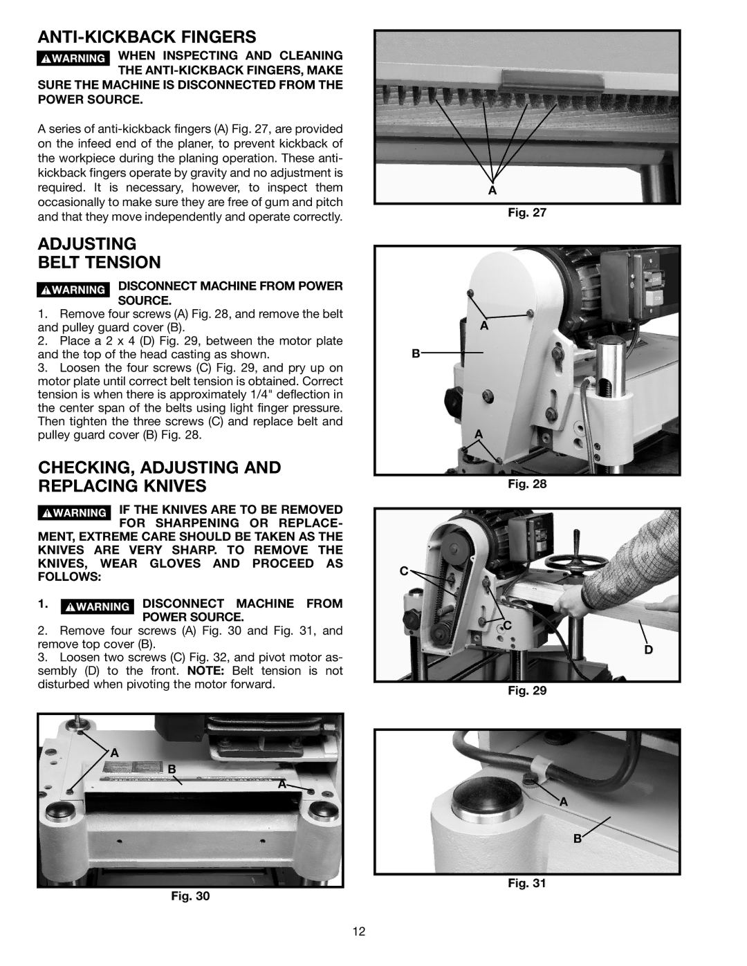
ANTI-KICKBACK FINGERS
![]() WHEN INSPECTING AND CLEANING THE
WHEN INSPECTING AND CLEANING THE
POWER SOURCE.
A series of
ADJUSTING
BELT TENSION
DISCONNECT MACHINE FROM POWER
SOURCE.
1.Remove four screws (A) Fig. 28, and remove the belt and pulley guard cover (B).
2.Place a 2 x 4 (D) Fig. 29, between the motor plate and the top of the head casting as shown.
3.Loosen the four screws (C) Fig. 29, and pry up on motor plate until correct belt tension is obtained. Correct tension is when there is approximately 1/4" deflection in the center span of the belts using light finger pressure. Then tighten the three screws (C) and replace belt and pulley guard cover (B) Fig. 28.
CHECKING, ADJUSTING AND REPLACING KNIVES
![]()
![]()
![]()
![]()
![]()
![]()
![]()
![]() IF THE KNIVES ARE TO BE REMOVED FOR SHARPENING OR REPLACE- MENT, EXTREME CARE SHOULD BE TAKEN AS THE
IF THE KNIVES ARE TO BE REMOVED FOR SHARPENING OR REPLACE- MENT, EXTREME CARE SHOULD BE TAKEN AS THE
KNIVES ARE VERY SHARP. TO REMOVE THE KNIVES, WEAR GLOVES AND PROCEED AS FOLLOWS:
1.![]()
![]()
![]()
![]()
![]()
![]()
![]()
![]() DISCONNECT MACHINE FROM POWER SOURCE.
DISCONNECT MACHINE FROM POWER SOURCE.
2.Remove four screws (A) Fig. 30 and Fig. 31, and remove top cover (B).
3.Loosen two screws (C) Fig. 32, and pivot motor as- sembly (D) to the front. NOTE: Belt tension is not disturbed when pivoting the motor forward.
A
B
A![]()
Fig. 30
A
Fig. 27
A
B
A
Fig. 28
C ![]()
C
D
Fig. 29
A
B
Fig. 31
12