Installation and connection instructions
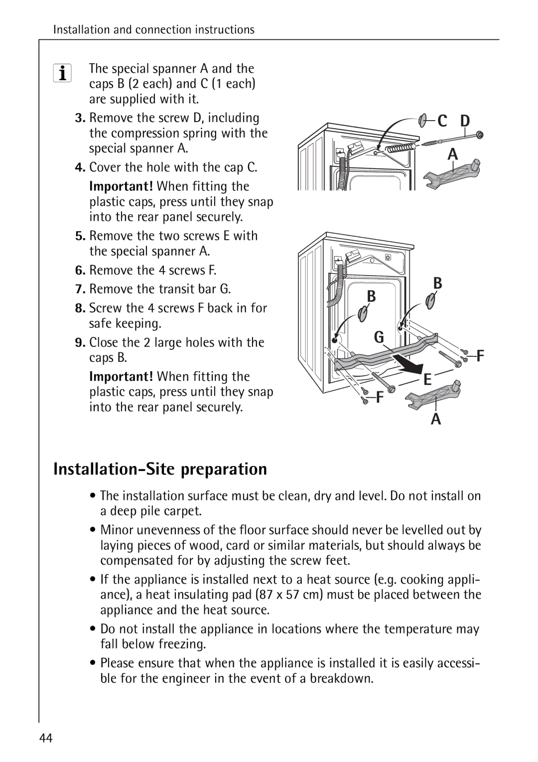
3 | The special spanner A and the |
| caps B (2 each) and C (1 each) |
are supplied with it.
3. Remove the screw D, including the compression spring with the special spanner A.
4. Cover the hole with the cap C.
Important! When fitting the plastic caps, press until they snap into the rear panel securely.
5.Remove the two screws E with
the special spanner A.
6. Remove the 4 screws F.
7. Remove the transit bar G.
8. Screw the 4 screws F back in for safe keeping.
9. Close the 2 large holes with the caps B.
Important! When fitting the plastic caps, press until they snap into the rear panel securely.
Installation-Site preparation
•The installation surface must be clean, dry and level. Do not install on a deep pile carpet.
•Minor unevenness of the floor surface should never be levelled out by laying pieces of wood, card or similar materials, but should always be compensated for by adjusting the screw feet.
•If the appliance is installed next to a heat source (e.g. cooking appli- ance), a heat insulating pad (87 x 57 cm) must be placed between the appliance and the heat source.
•Do not install the appliance in locations where the temperature may fall below freezing.
•Please ensure that when the appliance is installed it is easily accessi- ble for the engineer in the event of a breakdown.
44