Manuals
/
Electrolux
/
Kitchen Appliance
/
Range
Electrolux
C65030K operating instructions Removal, 25 mm
Models:
C65030K
1
36
40
40
Download
40 pages
51.26 Kb
33
34
35
36
37
38
39
40
<
>
Install
Connecting Diagram
Warranty
Dimension
1Problem Dirt
Appliance assembly
Rectifying faults
Timer
Heat Setting Selection + and
Safety When Cleaning
Page 36
Image 36
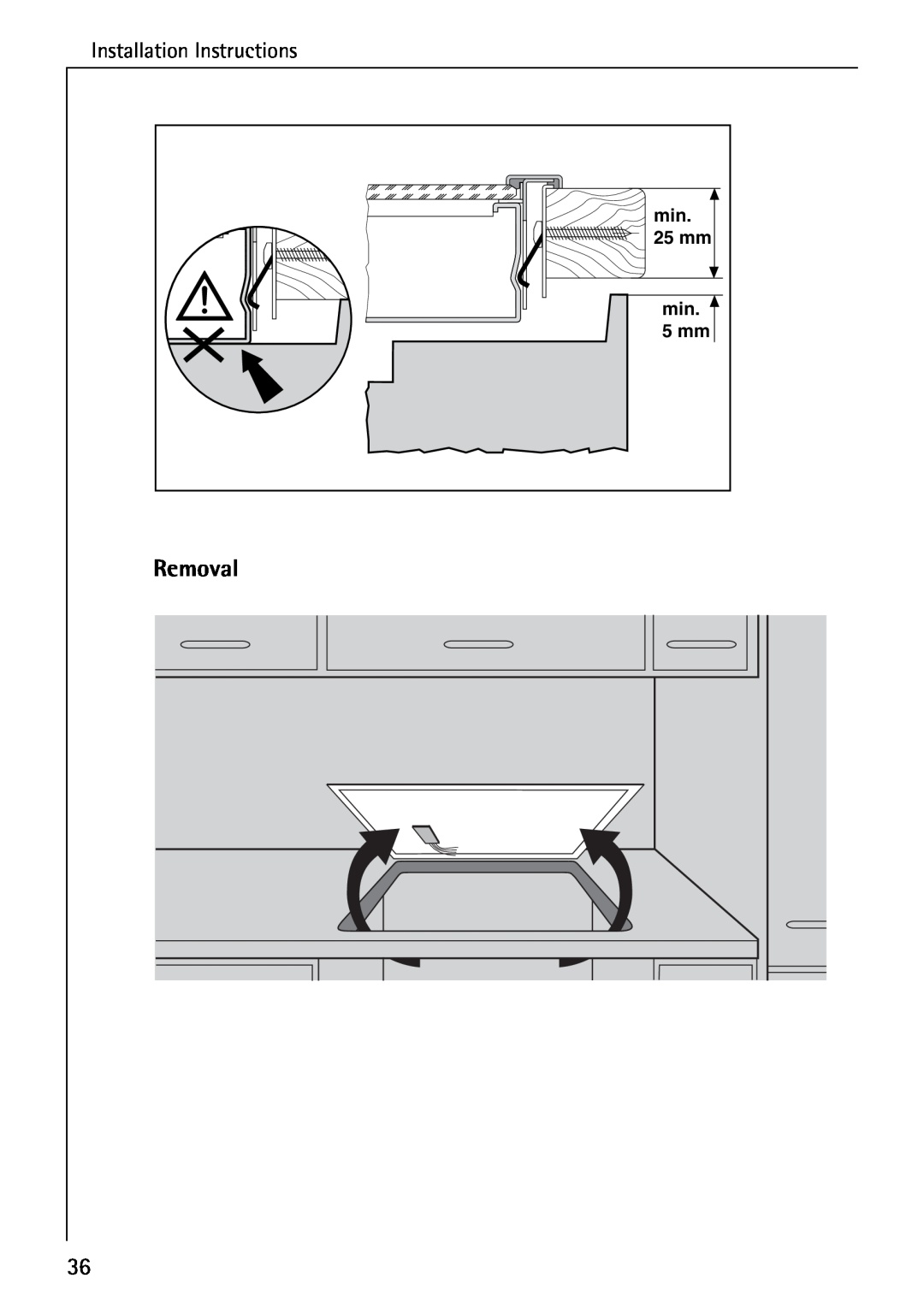
Installation Instructions
min.
25 mm
min.
5 mm
Removal
36
Page 35
Page 37
Page 36
Image 36
Page 35
Page 37
Contents
Installation and Operating Instructions
Ceramic Glass Hob
C65030K
The following symbols are used in the text
CONTENTS
What to do if
Warranty conditions
Service & Spare parts
1Safety
Electrical Safety
Child Safety
Safety During Use
Safety When Cleaning
To Avoid damaging your appliance
2Disposal
Disposing of the Packaging Material
Information on disposal
The Key Features of Your Appliance
Appliance assembly
Hob surface and control panel features
1 Cooking Zone Safety Cut-out
Cancelling the Safety Cut-out
Switching Off for Other Reasons
Digital displays
Before using for the first time
Initial Cleaning
Switching on the Appliance
Operating the hob
Switching Off the Appliance
Cooking Zone Selection
Heat Setting Selection + and
Switching off a cooking zone
Residual Heat Indicator
the appropriate cooking zones
is a risk of burns
Cooking with the automatic warm up function
Switching off a cooking zone
Cooking without the automatic warm up function
Locking/Unlocking the Control Panel
Timer
“egg timer”
Ending the timer function prematurely
Displaying the remaining cooking time
Using the timer to measure short periods of time
Uses, tables and tips
Pans
2 Energy saving tips
The automatic warm up function is suitable for
General notes
Typical Heat Settings
at an appropriate lower heat setting
Cleaning and care
Light Soiling
Stubborn Soiling
1Problem Dirt
Hob Frame
Rectifying faults
the cooking zones cannot be switched on?
What to do if
What do I do if
a cooking zone cannot be switched off?
a cooking zone cannot be switched on?
residual heat appears in the display?
f is shown in the display?
SERVICE & SPARE PARTS
PNC S No
08705
Customer Care
WARRANTY CONDITIONS
Great Britain
Guarantee Conditions
European Guarantee
INSTALLATION INSTRUCTIONS
Technical Data Appliance Dimensions
Cut-OutDimensions
Power Consumption
Regulations, Standards, Directives
1Safety Instructions for the Installer
Electrical Connection
tions and the terminal screws tightened securely
Connecting Diagram
Installation Instructions
Assembly
Installation Instructions
Removal
25 mm
5 mm
Page
Page
Page
AEG Hausgeräte GmbH Postfach D-90327Nürnberg
319 528 600 -A