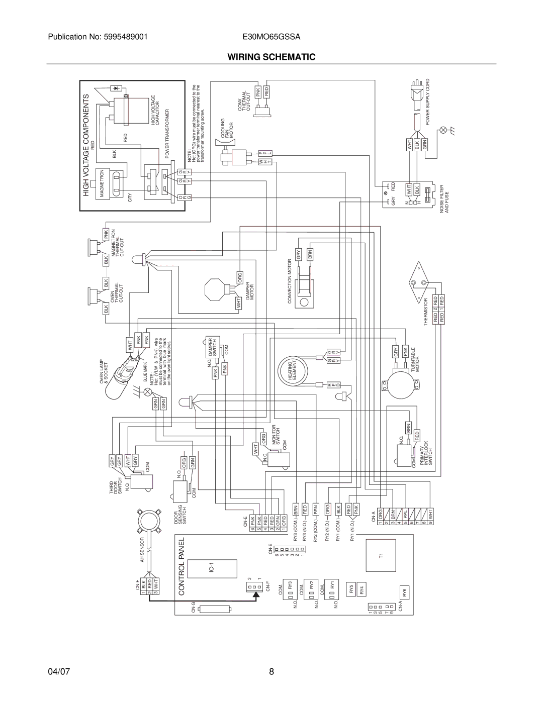
E30MO65GSSA, E30MO65G, E30M065GSS specifications
The Electrolux E30MO65G, E30MO65GSSA, and E30M065GSS are advanced built-in microwave convection ovens designed to elevate cooking experiences in modern kitchens. Combining elegance with functionality, these models offer a range of features aimed at enhancing convenience and versatility.One of the standout features of these Electrolux models is their innovative microwave convection cooking technology. This dual cooking method allows users to microwave dishes quickly while also browning and crisping them, producing perfectly cooked meals in less time. The convection fan circulates hot air throughout the oven, ensuring even cooking results and reducing cooking times.
The E30MO65G series showcases a spacious interior, accommodating large dishes and multiple cooking racks. This makes it ideal for families or those who entertain frequently. The ovens also come with a variety of pre-programmed cooking options, allowing users to select the desired setting for specific dishes, from popcorn to baked goods. This intelligent programming takes the guesswork out of cooking and delivers consistent results.
Another notable characteristic of these models is their user-friendly control panel. Featuring an intuitive touchpad interface, users can easily navigate through various settings and options. The bright display provides clear visibility, enabling cooks to monitor the progress of their meals with ease.
For those seeking energy efficiency, the Electrolux E30 series stands out. With their efficient design, these microwaves help reduce energy consumption without compromising performance. This commitment to sustainability aligns with Electrolux's brand ethos of creating environmentally friendly appliances.
Safety is also a key consideration in the design of the E30MO65G, E30MO65GSSA, and E30M065GSS. Features such as child lock controls and automatic shut-off mechanisms ensure peace of mind for busy households. The stainless-steel finishes of these models add a sleek, modern touch to any kitchen decor, making them an attractive addition to any culinary space.
In summary, the Electrolux E30MO65G, E30MO65GSSA, and E30M065GSS are state-of-the-art microwave convection ovens that blend innovative technology with practical design. With their versatility, user-friendly interfaces, energy efficiency, and stylish aesthetics, these ovens cater to the needs of today's health-conscious and busy cooks. Whether you're reheating leftovers or preparing gourmet meals, these Electrolux models are equipped to meet a wide array of culinary demands.

