Description of the appliance
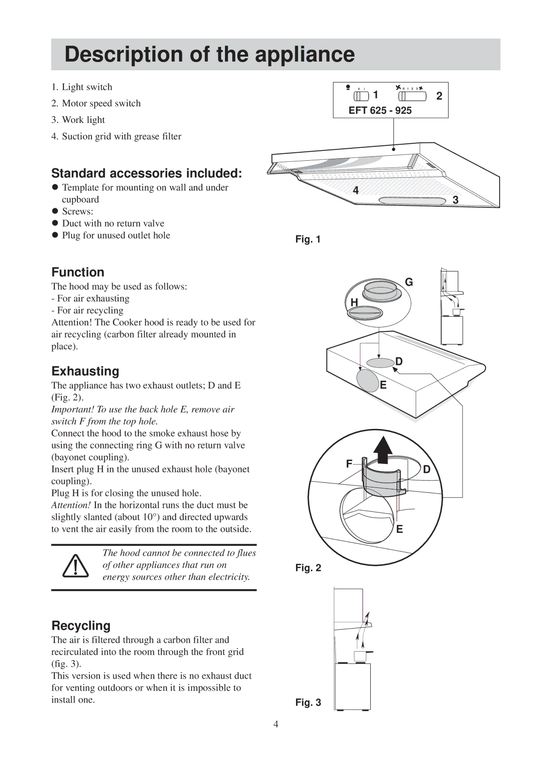
1.Light switch
2.Motor speed switch
3.Work light
4.Suction grid with grease filter
0 I | 0 I 2 3 |
12
EFT 625 - 925
Standard accessories included:
lTemplate for mounting on wall and under cupboard
lScrews:
lDuct with no return valve
lPlug for unused outlet hole
![]()
![]()
![]()
![]()
![]() 4
4![]()
![]()
![]()
![]()
![]()
![]()
![]()
![]()
![]()
![]()
![]()
![]()
![]()
![]()
![]()
![]()
![]()
![]()
![]()
![]()
![]()
![]()
![]()
3
Fig. 1
Function
The hood may be used as follows:
-For air exhausting
-For air recycling
Attention! The Cooker hood is ready to be used for air recycling (carbon filter already mounted in place).
Exhausting
The appliance has two exhaust outlets; D and E (Fig. 2).
Important! To use the back hole E, remove air switch F from the top hole.
Connect the hood to the smoke exhaust hose by using the connecting ring G with no return valve (bayonet coupling).
Insert plug H in the unused exhaust hole (bayonet coupling).
Plug H is for closing the unused hole.
Attention! In the horizontal runs the duct must be slightly slanted (about 10°) and directed upwards to vent the air easily from the room to the outside.
The hood cannot be connected to flues
of other appliances that run onFig. 2 energy sources other than electricity.
G
H
![]() D
D
![]() E
E
F
![]()
 D
D
E
Recycling
The air is filtered through a carbon filter and |
|
recirculated into the room through the front grid |
|
(fig. 3). |
|
This version is used when there is no exhaust duct |
|
for venting outdoors or when it is impossible to |
|
install one. | Fig. 3 |
4
