ITEMIZED PARTS LIST
ITEM | PART NO. | DESCRIPTION | |
NO. | |||
|
| ||
|
|
| |
1 | 100806740570 | Grommet | |
2 | 19037000 | Clip | |
3 | 23088C | Bracket Conduit | |
4 | 23100C | Panel Insulation Box (Rear) | |
5 | 23101C | Panel End | |
6 | 23104C | Box Insulation (Front) | |
7 | 26706C | Terminal Box | |
8 | 26707C | Grille | |
9 | 26708C | Cover Terminal Box | |
10 | 26709C | Rear Panel | |
11 | 27597C | Cover Insulation Box | |
12 | 28108C | Base Ass'y | |
13 | 30235C | Terminal Cover | |
14 | 30768C | Solenoid Valve | |
15 | 35880C | Overload | |
16 | 35882C | Cold Control | |
17 | 35895C | Cold Control Freeze Protect | |
18 | 35977C | Capacitor | |
19* | 35986C | Compressor Service Pak | |
20 | 30233C | Overload Spring | |
21 | 30234C | Clip Compressor | |
22 | 66226C | Condenser | |
23 | 66563C | Evaporator | |
24 | 70772C | Drain Plug | |
|
|
| |
| |||
|
|
| |
ITEM | PART NO. | DESCRIPTION | |
NO. | |||
|
| ||
|
|
| |
13 | 30560C | Terminal Cover | |
14 | 30781C | Solenoid Valve | |
15 | 35997C | Overload | |
18 | 36000C | Capacitor (run) | |
18A | 36003C | Capacitor (start) | |
19* | 36002C | Compressor Serv Pak | |
20 | 35998C | Overload Spring | |
- | 36001C | Relay | |
- | 35999C | Gasket | |
*INCLUDES RELAY & OVERLOAD. IF UNDER WARRANTY, REPLACE WITH SAME COMPRESSOR USED IN ORIGINAL ASSEMBLY.
NOTE: All correspondence pertaining to any of the above water cooler or orders for repair parts MUST include model number and serial number of cooler, name and part number of replacement part.
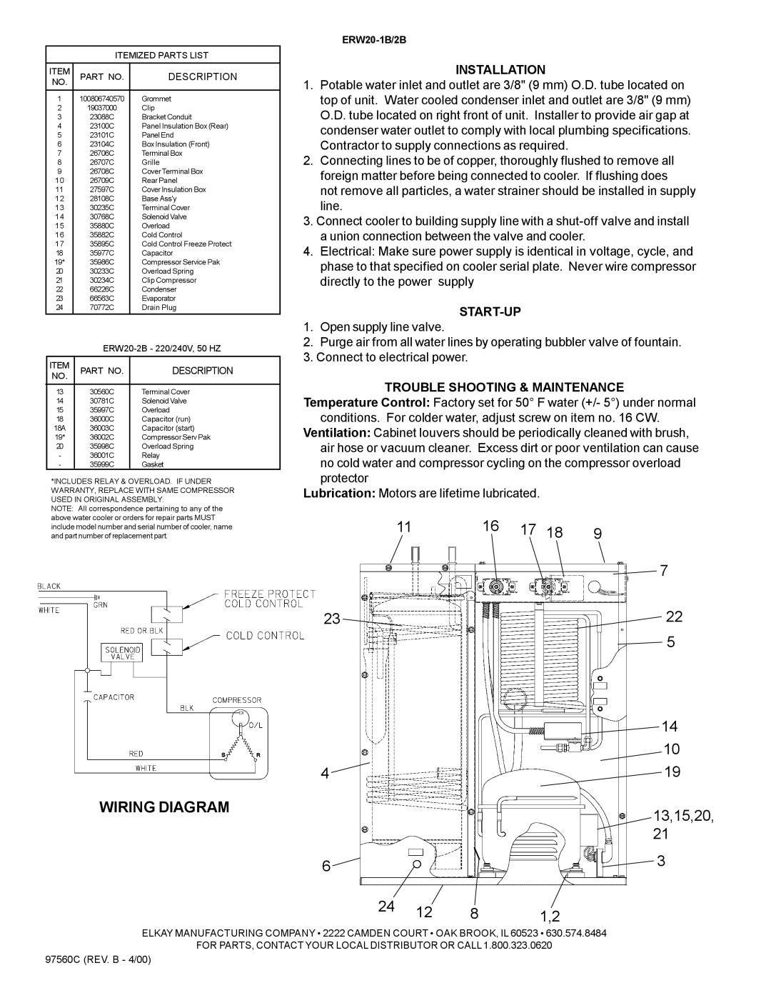
WIRING DIAGRAM
INSTALLATION
1.Potable water inlet and outlet are 3/8" (9 mm) O.D. tube located on top of unit. Water cooled condenser inlet and outlet are 3/8" (9 mm) O.D. tube located on right front of unit. Installer to provide air gap at condenser water outlet to comply with local plumbing specifications. Contractor to supply connections as required.
2.Connecting lines to be of copper, thoroughly flushed to remove all foreign matter before being connected to cooler. If flushing does not remove all particles, a water strainer should be installed in supply line.
3.Connect cooler to building supply line with a
4.Electrical: Make sure power supply is identical in voltage, cycle, and phase to that specified on cooler serial plate. Never wire compressor directly to the power supply
START-UP
1.Open supply line valve.
2.Purge air from all water lines by operating bubbler valve of fountain.
3.Connect to electrical power.
TROUBLE SHOOTING & MAINTENANCE Temperature Control: Factory set for 50° F water (+/- 5°) under normal
conditions. For colder water, adjust screw on item no. 16 CW. Ventilation: Cabinet louvers should be periodically cleaned with brush,
air hose or vacuum cleaner. Excess dirt or poor ventilation can cause no cold water and compressor cycling on the compressor overload protector
Lubrication: Motors are lifetime lubricated.
11 | 16 | 17 | 18 | 9 |
|
|
|
| 7 |
23 |
|
|
| 22 |
|
|
|
| 5 |
14
10
4 | 19 |
13,15,20,
21
6 |
|
| 3 |
|
|
| |
24 | 12 | 8 | 1,2 |
|
ELKAY MANUFACTURING COMPANY • 2222 CAMDEN COURT • OAK BROOK, IL 60523 • 630.574.8484
FOR PARTS, CONTACT YOUR LOCAL DISTRIBUTOR OR CALL 1.800.323.0620
97560C (REV. B - 4/00)