Cello Cable Kits
5. General I/O J1 (CBL-CELIO1-5)
The digital input cable is a
Pin | Color | Signal | Pair | Function | Pin Position | |
1 | Orange | IN1 | pair | Programmable input 1 | 15 Pin | |
2 | Cyan | IN2 | Programmable input 2 | |||
| ||||||
3 | Purple | IN3 |
| Programmable input 3 | Socket | |
pair |
| |||||
8 | Black | IN8 | Programmable input 8 |
| ||
|
| |||||
4 | Gray | OUT2 | pair | Programmable output 2 |
| |
5 | Pink | OUT3 | Programmable output 3 |
| ||
|
| |||||
6 | Blue | IN4 | pair | Programmable input 4 |
| |
7 | Red | IN7 | Programmable input 7 |
| ||
|
| |||||
9 | White/ | INRET |
| General input return |
| |
Yellow |
|
| ||||
|
|
|
|
| ||
10 | White/ |
| Programmable output |
| ||
Red |
| return 2 & 3 |
| |||
|
|
|
| |||
11 | Yellow | OUT4 | pair | Programmable output 4 |
| |
13 | Green | OUT5 | Programmable output 5 |
| ||
|
| |||||
12 | White/ |
| Programmable output |
| ||
Black |
| return 4 & 5 |
| |||
|
|
|
| |||
14 | Brown | OUT1 |
| Programmable output 1 |
| |
15 | White | OUTRET 1 | pair | Programmable output |
| |
| return 1 |
| ||||
|
|
|
|
|
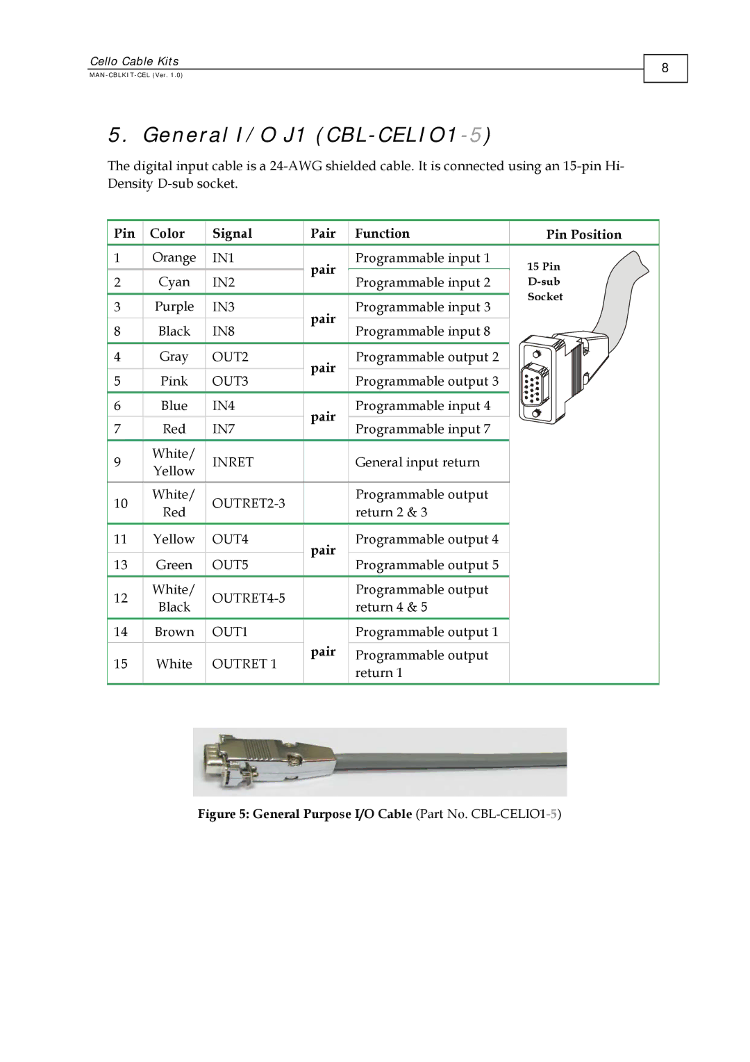
Figure 5: General Purpose I/O Cable (Part No. CBL-CELIO1-5)
8