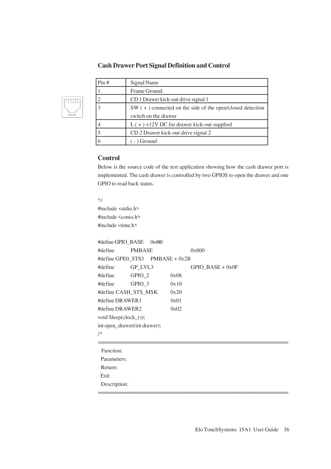
Cash Drawer Port Signal Definition and Control
Pin # | Signal Name |
1Frame Ground
2CD 1 Drawer
3SW ( + ) connected on the side of the open/closed detection switch on the drawer
4L ( + ) +12V DC for drawer
5CD 2 Drawer
6( - ) Ground
Control
Below is the source code of the test application showing how the cash drawer port is implemented. The cash drawer is controlled by two GPIOS to open the drawer and one GPIO to read back status.
*/
#include <stdio.h> #include <conio.h> #include <time.h>
#define GPIO_BASE | 0x480 |
| |
#define | PMBASE | 0x800 | |
#define GPE0_STS3 | PMBASE + 0x2B | ||
#define | GP_LVL3 | GPIO_BASE + 0x0F | |
#define | GPIO_2 |
| 0x08 |
#define | GPIO_3 |
| 0x10 |
#define CASH_STS_MSK | 0x20 | ||
#define DRAWER1 |
| 0x01 | |
#define DRAWER2 |
| 0x02 | |
void Sleep(clock_t t); |
|
| |
int open_drawer(int drawer); /*
=============================================================================
Function:
Parameters:
Return:
Exit:
Description:
=============================================================================
Elo TouchSystems 15A1 User Guide 36
