C H A P T E R
TECHNICAL DESCRIPTION
Block Diagram
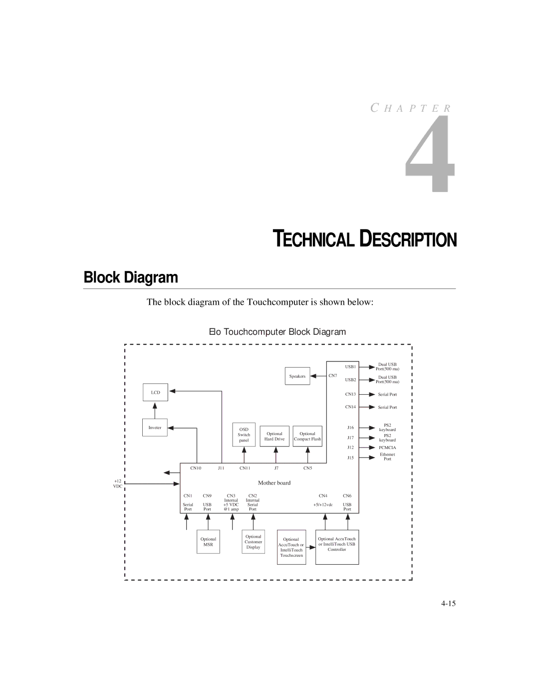
The block diagram of the Touchcomputer is shown below:
Elo Touchcomputer Block Diagram
LCD
Inveter
+12
VDC
|
|
|
|
|
|
| USB1 |
|
|
|
|
| Speakers | CN7 | USB2 |
|
|
|
|
|
|
| |
|
|
|
|
|
|
| CN13 |
|
|
|
|
|
|
| CN14 |
|
|
| OSD |
|
|
| J16 |
|
|
| Optional | Optional |
| ||
|
| Switch | J17 | ||||
|
|
| panel | Hard Drive | Compact Flash | ||
|
|
|
|
|
|
| J12 |
|
|
|
|
|
|
| J15 |
CN10 | J11 | CN11 | J7 | CN5 |
|
| |
|
|
| Mother board |
|
| ||
CN1 | CN9 | CN3 | CN2 |
|
| CN4 | CN6 |
Serial | USB | Internal | Internal |
|
| +5/+12vdc | USB |
+5 VDC | Serial |
|
| ||||
Port | Port | @1 amp | Port |
|
|
| Port |
| Optional |
| Optional | Optional | Optional AccuTouch | ||
|
| Customer | |||||
| MSR |
| AccuTouch or | or IntelliTouch USB | |||
|
| Display | |||||
|
|
| IntelliTouch | Controller | |||
|
|
|
| ||||
|
|
|
| Touchscreen |
|
| |
Dual USB
Port(500 ma)
Dual USB
Port(500 ma)
Serial Port
Serial Port
PS2
keyboard
PS2
keyboard
PCMCIA
Ethemet
Port