10-30kVA specifications
The Emerson 10-30 kVA, 208V uninterruptible power supply (UPS) solution is a robust system designed to provide reliable power protection for critical applications in commercial and industrial settings. This UPS is ideal for safeguarding IT equipment, communication systems, and other sensitive electronics against power disturbances and interruptions.One of the standout features of the Emerson 10-30 kVA UPS is its modular design, allowing for flexibility and scalability. This means that as the power needs of a facility grow, the UPS can be easily expanded without requiring a complete system overhaul. This modularity contributes to a more efficient use of resources and minimizes operational costs.
The UPS also incorporates advanced technologies such as double-conversion online architecture, which provides the highest level of power quality. This technology ensures that the output power is consistently clean and stable, effectively eliminating harmful voltage fluctuations and frequency variations. Consequently, connected load receives a pure sine wave output, preventing potential damage or operational issues with sensitive equipment.
Another key feature is the high efficiency rating of the Emerson UPS, which exceeds 95 percent in typical operating conditions. This high efficiency translates to reduced energy costs and a smaller carbon footprint, aligning with modern sustainability goals. The cooling system is designed to be efficient as well, ensuring optimal performance while maintaining a compact footprint.
The user-friendly interface enhances operability, featuring an intuitive LCD display that allows for easy monitoring of critical power parameters. Users can access real-time data related to battery health, load levels, and operational status, which aids in effective management of the power supply.
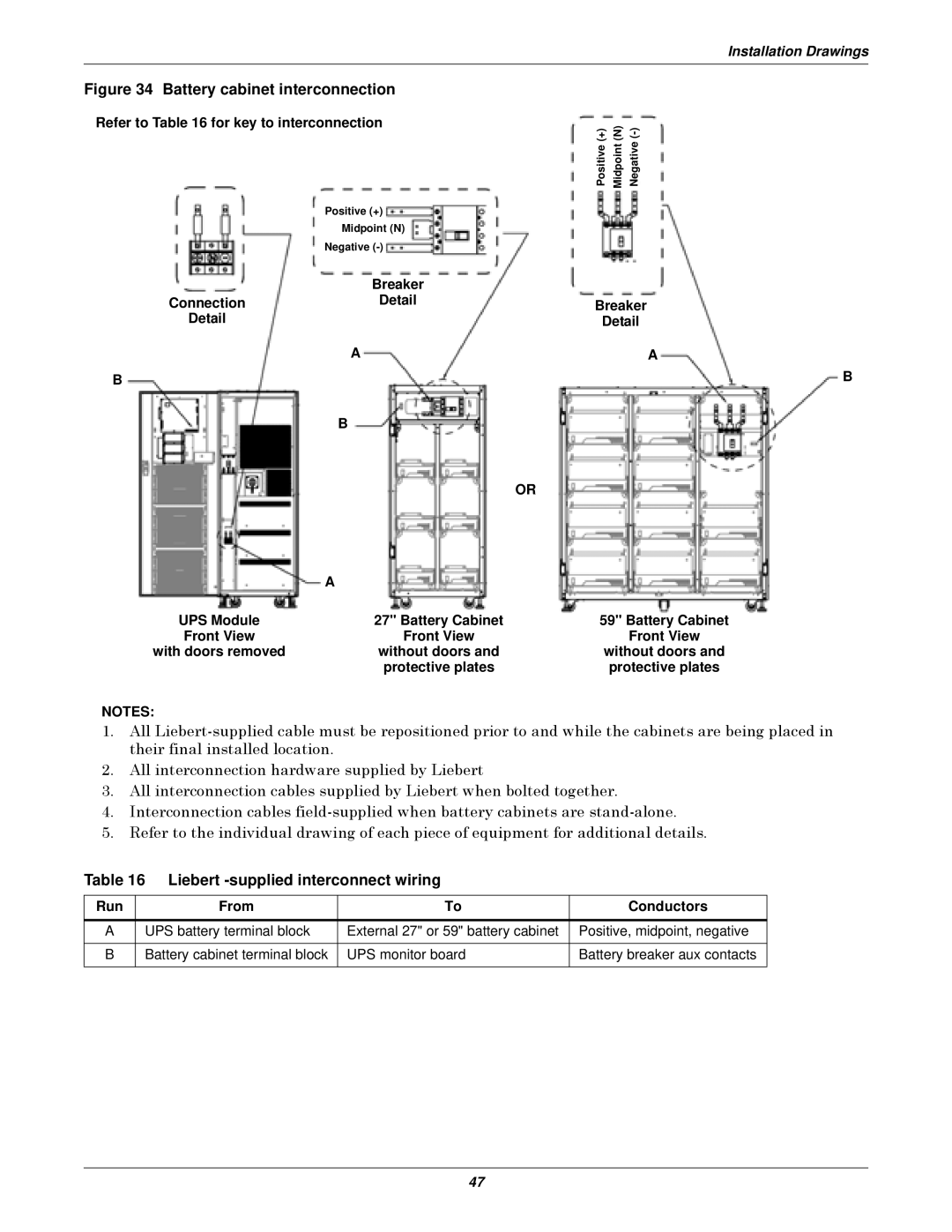
Battery management is another critical aspect of the Emerson UPS. It employs advanced battery management technologies to ensure optimal battery life and performance. Features such as intelligent battery testing and monitoring help predict potential battery failures before they occur, allowing for proactive maintenance and minimized downtime.
In summary, the Emerson 10-30 kVA, 208V UPS offers a combination of modularity, high efficiency, advanced technologies, and effective power management features that cater to the demanding needs of critical applications. With its reliable performance and user-friendly operation, this UPS solution is an excellent choice for organizations looking to protect their valuable equipment from power disturbances.

