Series 185

FUNCTIONAL TEST

After installing the Series 185 automatic transfer switch (ATS) perform the following three–part functional test.

1 --- Manual Operation

A handle is provided on the transfer switch for mainte- nance purposes only. Manual operation of the transfer switch should be checked before it is energized (operated electrically).

Do not manually operate the transfer switch until both power sources are disconnected: open both circuit breakers.

1.Turn OFF both the utility and generator circuit breakers feeding the ATS. Verify that ALL POWER

IS OFF!

2.100–230 A

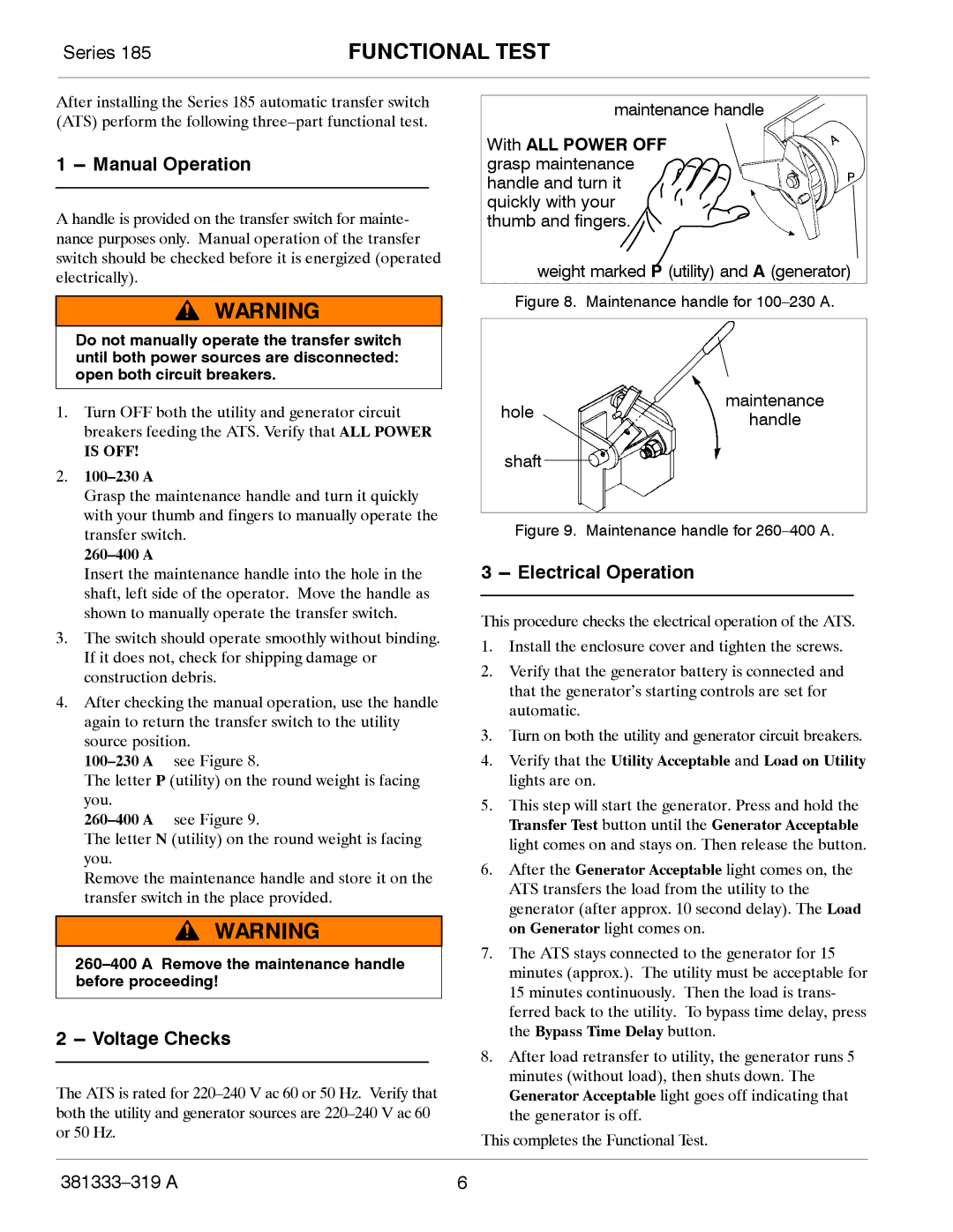
Grasp the maintenance handle and turn it quickly with your thumb and fingers to manually operate the transfer switch.

260–400 A

Insert the maintenance handle into the hole in the shaft, left side of the operator. Move the handle as shown to manually operate the transfer switch.

3.The switch should operate smoothly without binding. If it does not, check for shipping damage or construction debris.

4.After checking the manual operation, use the handle again to return the transfer switch to the utility source position.

100–230 A see Figure 8.

The letter P (utility) on the round weight is facing you.

260–400 A see Figure 9.

The letter N (utility) on the round weight is facing you.

Remove the maintenance handle and store it on the transfer switch in the place provided.

260–400 A Remove the maintenance handle before proceeding!

2 --- Voltage Checks

The ATS is rated for 220–240 V ac 60 or 50 Hz. Verify that both the utility and generator sources are 220–240 V ac 60 or 50 Hz.

maintenance handle

With ALL POWER OFF grasp maintenance handle and turn it quickly with your thumb and fingers.

weight marked P (utility) and A (generator)

Figure 8. Maintenance handle for 100–230 A.

hole


maintenance


handle


shaft


Figure 9. Maintenance handle for 260–400 A.

3 --- Electrical Operation

This procedure checks the electrical operation of the ATS.

1.Install the enclosure cover and tighten the screws.

2.Verify that the generator battery is connected and that the generator’s starting controls are set for automatic.

3.Turn on both the utility and generator circuit breakers.

4.Verify that the Utility Acceptable and Load on Utility lights are on.

5.This step will start the generator. Press and hold the Transfer Test button until the Generator Acceptable light comes on and stays on. Then release the button.

6.After the Generator Acceptable light comes on, the ATS transfers the load from the utility to the generator (after approx. 10 second delay). The Load on Generator light comes on.

7.The ATS stays connected to the generator for 15 minutes (approx.). The utility must be acceptable for 15 minutes continuously. Then the load is trans- ferred back to the utility. To bypass time delay, press the Bypass Time Delay button.

8.After load retransfer to utility, the generator runs 5 minutes (without load), then shuts down. The Generator Acceptable light goes off indicating that the generator is off.

This completes the Functional Test.

381333–319 A

6

Page 8
Image 8
Emerson 185 manual Functional Test, Manual Operation, Voltage Checks, Electrical Operation

185 specifications

The Emerson 185 is an advanced and versatile automated control system that stands out for its exceptional performance and reliability in various industrial applications. Designed to streamline operations, improve efficiency, and ensure safety, the Emerson 185 integrates cutting-edge technologies to address the complex demands of modern industries.

One of the main features of the Emerson 185 is its modular architecture, which allows for easy scalability and customization. This flexibility enables operators to adapt the system according to their specific requirements, whether for small-scale processes or large, intricate industrial plants. The modular design simplifies upgrades and maintenance, ensuring that businesses can stay ahead in today's fast-paced environment.

Incorporating advanced control algorithms, the Emerson 185 enhances process automation. Its robust predictive analytics capabilities allow for real-time monitoring and data analysis, which aid in optimizing performance and reducing downtime. With this technology at their disposal, operators can anticipate potential issues and take proactive measures, resulting in improved operational efficiency.

The Emerson 185 is also equipped with user-friendly interfaces that facilitate intuitive operation. Its advanced graphical displays and customizable dashboards provide operators with comprehensive visibility into process performance. This feature allows for informed decision-making and quick responses to unexpected situations, ultimately contributing to increased productivity.

Another significant characteristic of the Emerson 185 is its emphasis on safety and environmental compliance. The system includes built-in safety features and adheres to international standards, ensuring that operations not only meet regulatory requirements but also promote a safer working environment. The emphasis on sustainability aligns with the growing expectation for environmental responsibility in industrial practices.

Communication is a key component of the Emerson 185. The system supports various communication protocols, enabling seamless integration with existing infrastructure and third-party devices. This interoperability ensures that organizations can leverage their current investments while enhancing the overall control capabilities of their processes.

In summary, the Emerson 185 combines modularity, advanced automation, user-friendly interfaces, safety features, and effective communication to deliver a comprehensive solution for modern industrial challenges. Its focus on improving efficiency and ensuring reliability makes it a valuable asset for businesses aiming to optimize their operations and maintain a competitive edge in today's ever-evolving market. With the Emerson 185, organizations can confidently navigate the complexities of modern industrial environments.