WIRING DIAGRAMS

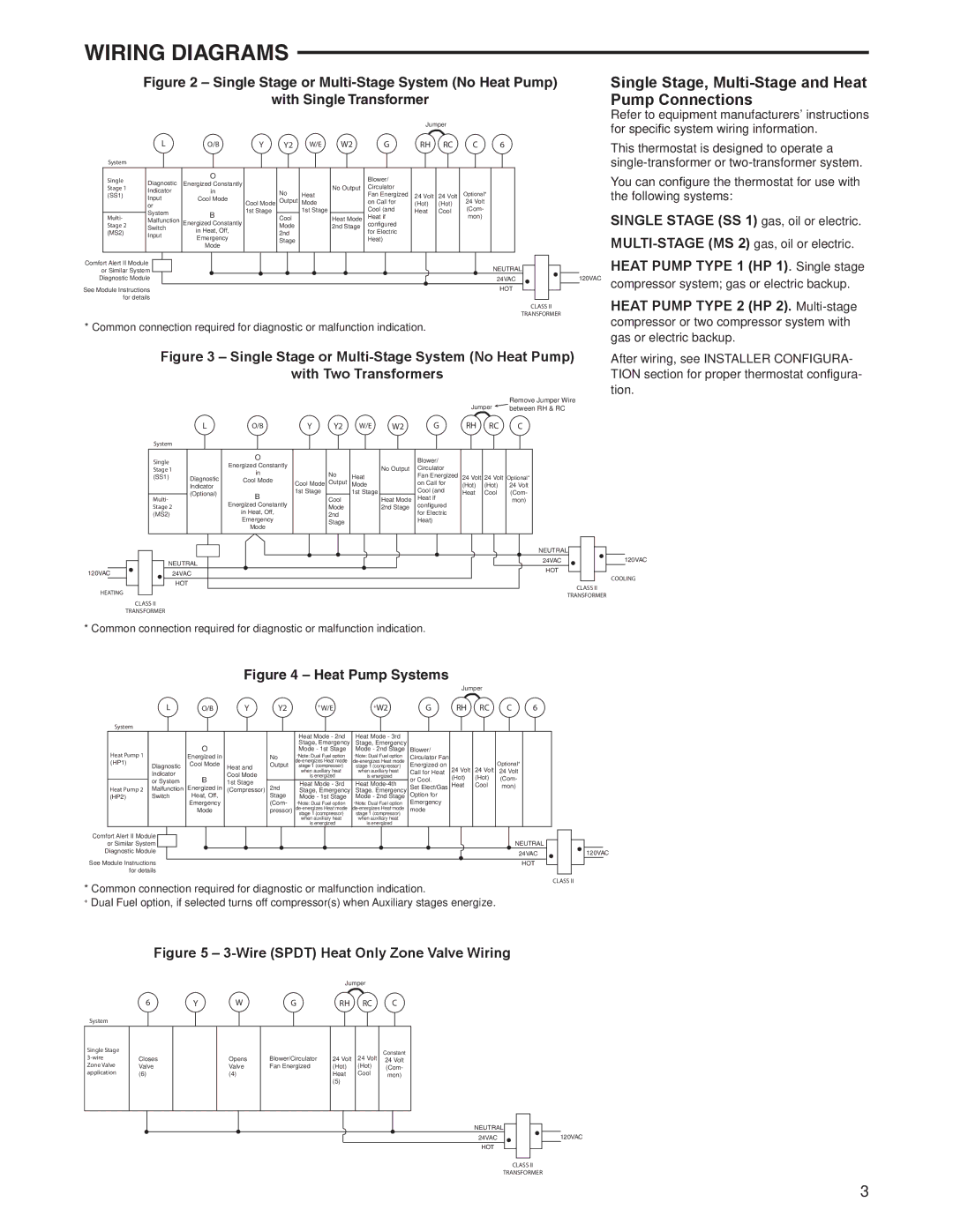
Figure 2 – Single Stage or Multi-Stage System (No Heat Pump)

with Single Transformer

Jumper


L

O/B

Y

Y2

W/E

W2

G

RH

RC

C

6

System


Single

Diagnostic

O


Blower/


Energized Constantly


Stage 1


No Output

Circulator


Indicator

in


No


(SS1)


Heat


Fan Energized

24 Volt

24 Volt

Optional*


Input

Cool Mode


Cool Mode

Output

Mode


on Call for

(Hot)

(Hot)

24 Volt


or


System

B

1st Stage


1st Stage


Cool (and

Heat

Cool

(Com-


Multi-

Malfunction


Cool


Heat Mode

Heat if


mon)


Stage 2

Switch

Energized Constantly


Mode


2nd Stage

configured


in Heat, Off,


(MS2)

Input


2nd


for Electric


Emergency


Stage


Heat)


Mode


Single Stage, Multi-Stage and Heat Pump Connections

Refer to equipment manufacturers' instructions for specific system wiring information.

This thermostat is designed to operate a single-transformer or two-transformer system.

You can configure the thermostat for use with the following systems:

SINGLE STAGE (SS 1) gas, oil or electric.

MULTI-STAGE (MS 2) gas, oil or electric.

or Similar System

NEUTRAL


HEAT PUMP TYPE 1 (HP 1). Single stage

Comfort Alert II Module


Diagnostic Module

24VAC

120VAC

compressor system; gas or electric backup.

See Module Instructions

HOT


for details


HEAT PUMP TYPE 2 (HP 2). Multi-stage


CLASS II


TRANSFORMER


compressor or two compressor system with

* Common connection required for diagnostic or malfunction indication.


gas or electric backup.


Figure 3 – Single Stage or Multi-Stage System (No Heat Pump)

with Two Transformers

Remove Jumper Wire

Jumper between RH & RC

After wiring, see INSTALLER CONFIGURA- TION section for proper thermostat configura- tion.


L


O/B

Y

Y2

W/E

W2

G

RH

RC

C


System


Single


O


Blower/


Energized Constantly


Stage 1


No Output

Circulator


in


No


(SS1)


Diagnostic


Heat


Fan Energized

24 Volt

24 Volt

Optional*


Cool Mode


Indicator


Cool Mode

Output

Mode


on Call for

(Hot)

(Hot)

24 Volt


(Optional)


B

1st Stage


1st Stage


Cool (and

Heat

Cool

(Com-


Multi-


Cool


Heat Mode

Heat if


mon)


Stage 2


Energized Constantly


Mode


2nd Stage

configured


(MS2)


in Heat, Off,


2nd


for Electric


Emergency


Stage


Heat)


Mode


NEUTRAL


24VAC


120VAC


NEUTRAL


HOT


120VAC


24VAC


COOLING


HOT


CLASS II


HEATING


TRANSFORMER


CLASS II


TRANSFORMER


* Common connection required for diagnostic or malfunction indication.

Figure 4 – Heat Pump Systems


Jumper


L

O/B

Y

Y2

+W/E

+W2

G

RH

RC

C

6

System


Heat Mode - 2nd

Heat Mode - 3rd


O


Stage, Emergency

Stage, Emergency


Heat Pump 1


Mode - 1st Stage

Mode - 2nd Stage

Blower/


Energized in


No

+Note: Dual Fuel option

+Note: Dual Fuel option

Circulator Fan


(HP1)

Diagnostic

Cool Mode

Heat and

Output

de-energizes Heat mode de-energizes Heat mode

Energized on


Optional*


stage 1 (compressor)

stage 1 (compressor)

24 Volt

24 Volt


Indicator


Cool Mode


when auxiliary heat

when auxiliary heat

Call for Heat

24 Volt


B


is energized

is energized

(Hot)

(Hot)

(Com-


or System

1st Stage


or Cool.


Heat Mode - 3rd

Heat Mode-4th


Heat Pump 2

Malfunction

Energized in

2nd

Set Elect/Gas Heat

Cool

mon)


(Compressor)

Stage, Emergency

Stage. Emergency


(HP2)

Switch

Heat, Off,


Stage

Mode - 1st Stage

Mode - 2nd Stage

Option for


Emergency


(Com- +Note: Dual Fuel option

+Note: Dual Fuel option

Emergency


Mode


pressor)

de-energizes Heat mode de-energizes Heat mode

mode


stage 1 (compressor)

stage 1 (compressor)


when auxiliary heat

when auxiliary heat


is energized

is energized


Comfort Alert II Module


or Similar System

NEUTRAL

Diagnostic Module

24VAC

See Module Instructions

HOT

120VAC

for details

* Common connection required for diagnostic or malfunction indication.

CLASS II

+Dual Fuel option, if selected turns off compressor(s) when Auxiliary stages energize.

Figure 5 – 3-Wire (SPDT) Heat Only Zone Valve Wiring


Jumper


6

Y

W

G

RH RC

C

System

Single Stage 3-wire Zone Valve application

Closes

Valve

(6)

Opens

Valve

(4)

Blower/Circulator

Fan Energized

24 Volt

24 Volt

Constant

24 Volt

(Hot)

(Hot)

(Com-

Heat

Cool

mon)

(5)


NEUTRAL

24VAC

HOT

120VAC

CLASS II

TRANSFORMER

3

Page 3
Image 3
Emerson 1F95EZ-0671 specifications Wiring Diagrams, Heat Pump Type 1 HP 1. Single stage, Heat Pump Type 2 HP 2. Multi-stage

1F95EZ-0671 specifications

The Emerson 1F95EZ-0671 is a state-of-the-art thermostat designed for maximum efficiency and user adaptability. This device stands out in the market due to its innovative features that cater to both residential and light commercial applications.

One of the primary features of the Emerson 1F95EZ-0671 is its advanced touchscreen interface. The large, clear display provides users with an intuitive experience for easy programming and monitoring. The backlit screen ensures visibility even in low-light conditions, making it user-friendly at any hour.

A standout technology featured in the 1F95EZ-0671 is its Wi-Fi connectivity. This allows users to remotely control their heating, ventilation, and air conditioning (HVAC) systems through a smartphone app. The compatibility with both iOS and Android devices helps users maintain optimal temperatures from virtually anywhere. This modern convenience not only enhances comfort but also promotes energy savings through effective temperature management.

The thermostat incorporates smart learning technology, which enables it to adapt to user behavior and preferences. By analyzing daily patterns, the Emerson thermostat can optimize heating and cooling schedules, thus maximizing energy efficiency and comfort. This feature minimizes energy waste, leading to lower utility bills over time.

Another significant characteristic of the Emerson 1F95EZ-0671 is its multi-stage heating and cooling capabilities. Catering to diverse HVAC setups, it can control multi-stage systems, ensuring that home environments remain comfortable regardless of external conditions. This broad compatibility makes it an ideal choice for a range of systems installed in various homes and buildings.

Energy efficiency is enhanced further through features like the adaptive recovery technology. This ensures that the system intelligently adjusts to achieve the desired temperature by the scheduled time, which results in decreased energy consumption.

Installation is made simple through the device's compatibility with a wide range of heating and cooling systems, while the easy-to-follow setup guide ensures that both professional and DIY technicians can install it effortlessly.

Overall, the Emerson 1F95EZ-0671 combines modern technology with user-friendly design elements, making it a popular choice for those seeking an advanced yet easy-to-use thermostat. With its emphasis on energy efficiency, smart features, and versatile compatibility, it represents a significant advancement in home climate control technology.