►System Applications
Cycle Pilot System
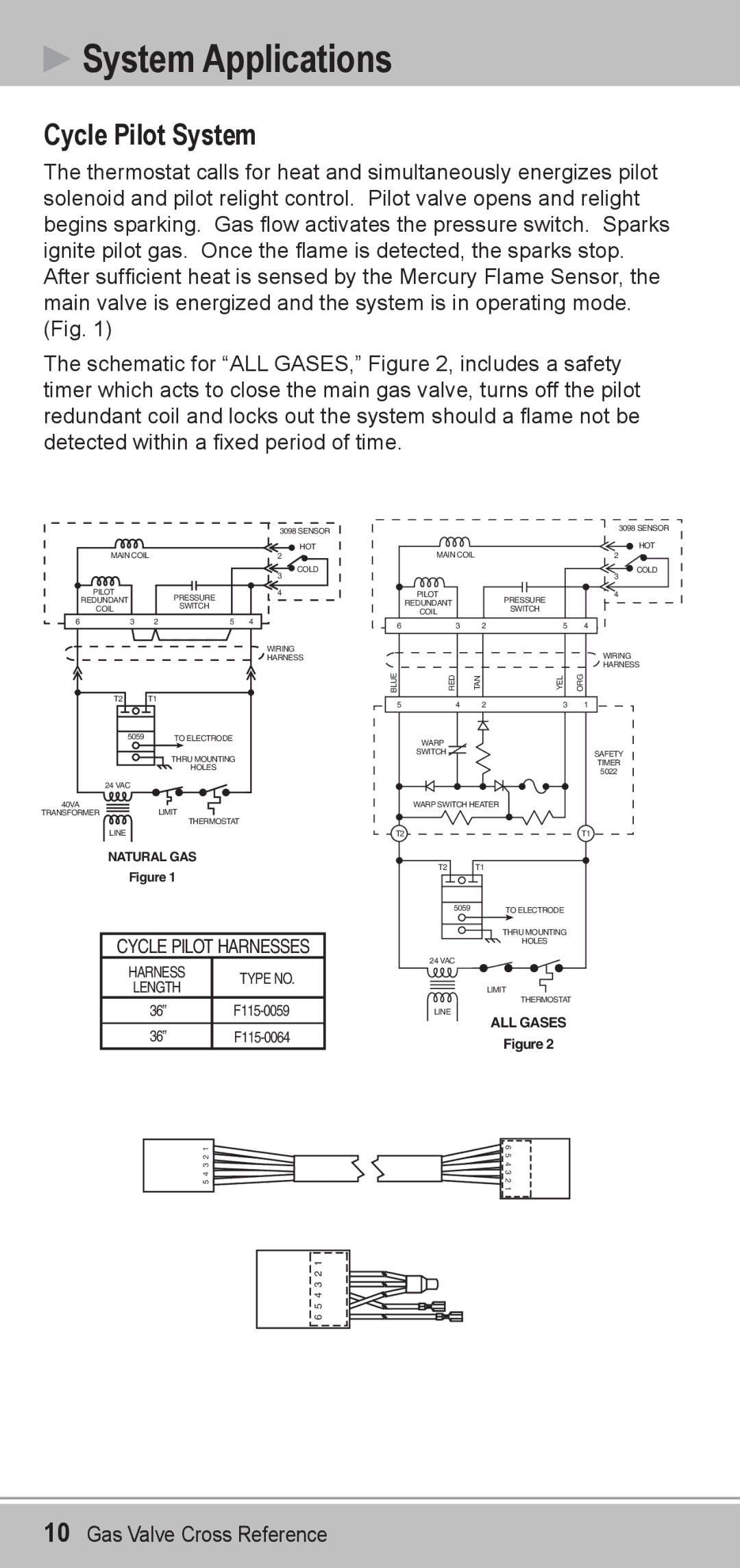
The thermostat calls for heat and simultaneously energizes pilot solenoid and pilot relight control. Pilot valve opens and relight begins sparking. Gas flow activates the pressure switch. Sparks ignite pilot gas. Once the flame is detected, the sparks stop. After sufficient heat is sensed by the Mercury Flame Sensor, the main valve is energized and the system is in operating mode. (Fig. 1)
The schematic for “ALL GASES,” Figure 2, includes a safety timer which acts to close the main gas valve, turns off the pilot redundant coil and locks out the system should a flame not be detected within a fixed period of time.
|
|
|
| 3098 SENSOR | |
| MAIN COIL |
| 2 | HOT | |
|
|
| |||
|
|
|
| 3 | COLD |
|
|
|
|
| |
| PILOT |
| PRESSURE | 4 |
|
| REDUNDANT |
|
|
| |
|
| SWITCH |
|
| |
| COIL |
|
|
| |
|
|
|
|
| |
6 | 3 | 2 | 5 | 4 |
|
|
|
|
| WIRING |
|
|
|
|
| HARNESS | |
| T2 | T1 |
|
|
|
| 5059 |
| TO ELECTRODE |
|
|
THRU MOUNTING
HOLES
24 VAC
40VA
TRANSFORMERLIMIT ![]() THERMOSTAT
THERMOSTAT
LINE
NATURAL GAS
Figure 1
CYCLE PILOT HARNESSES
HARNESS | TYPE NO. | |
LENGTH | ||
|
3098 SENSOR
| MAIN COIL |
|
| HOT | |
|
| 2 |
| ||
|
|
|
| 3 | COLD |
|
|
|
|
| |
| PILOT |
| PRESSURE | 4 |
|
| REDUNDANT |
|
|
| |
|
| SWITCH |
|
| |
| COIL |
|
|
| |
|
|
|
|
| |
6 | 3 | 2 | 5 | 4 |
|
|
|
|
| WIRING |
|
|
|
|
| HARNESS | |
BLUE | RED | TAN | YEL | ORG |
|
5 | 4 | 2 | 3 | 1 |
|
| WARP |
|
|
|
|
| SWITCH |
|
| SAFETY |
|
|
|
|
| TIMER |
|
|
|
|
| 5022 |
|
| WARP SWITCH HEATER |
|
|
| |
T2 |
|
|
| T1 |
|
| T2 | T1 |
|
|
|
| 5059 |
| TO ELECTRODE |
|
|
|
|
| THRU MOUNTING |
|
|
|
|
| HOLES |
|
|
24 VAC
LIMIT
36” | |
36” |
LINE
THERMOSTAT
ALL GASES
Figure 2
5 4 3 2 1![]()
6 5 4 3 2 1
![]()
![]()
![]() 6 5 4 3 2 1
6 5 4 3 2 1
10Gas Valve Cross Reference
