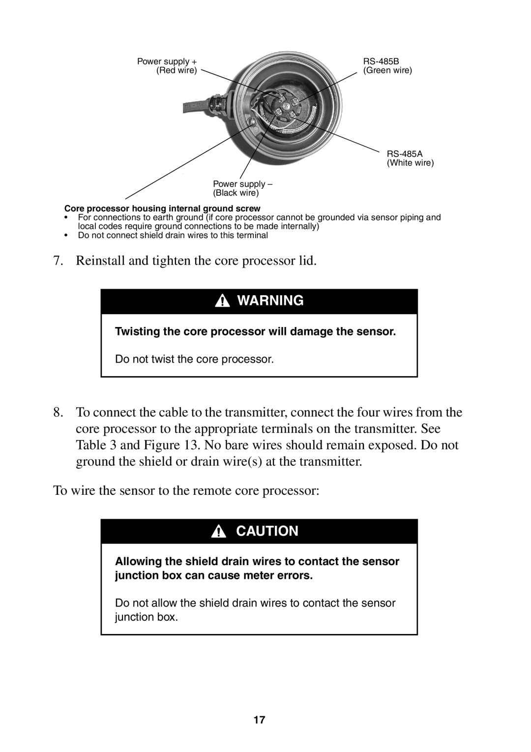
Power supply + | |
(Red wire) | (Green wire) |
Power supply – (Black wire)
Core processor housing internal ground screw
•For connections to earth ground (if core processor cannot be grounded via sensor piping and local codes require ground connections to be made internally)
•Do not connect shield drain wires to this terminal
7.Reinstall and tighten the core processor lid.
![]()
![]()
![]() WARNING
WARNING
Twisting the core processor will damage the sensor.
Do not twist the core processor.
8.To connect the cable to the transmitter, connect the four wires from the core processor to the appropriate terminals on the transmitter. See Table 3 and Figure 13. No bare wires should remain exposed. Do not ground the shield or drain wire(s) at the transmitter.
To wire the sensor to the remote core processor:
CAUTION
Allowing the shield drain wires to contact the sensor junction box can cause meter errors.
Do not allow the shield drain wires to contact the sensor junction box.
17