398, 397, 396VP, 398VP, 396 specifications
Emerson offers a wide range of advanced process control instruments, and among them, the Emerson 396, 398VP, 396VP, 397, and 398 stand out for their precision, reliability, and versatility. These models are designed to cater to the demanding needs of industrial applications, particularly in the areas of pressure, temperature, and flow measurement.The Emerson 396 series focuses on providing robust pressure and temperature measurement solutions. One of its standout features is its digital manometer functionality, which allows for precise measurement of differential pressure. This makes it an excellent choice for HVAC applications and other industrial processes where accuracy is critical. The 396 model is equipped with advanced signal processing capabilities, allowing for the adjustment of sensitivities and ranges according to specific application needs.
Moving on to the 398VP and 396VP models, these variants incorporate advanced validation features that ensure data integrity and accuracy. They are designed with user-friendly interfaces that not only simplify operation but also enhance user experience. The 398VP model, in particular, is celebrated for its versatility, as it can operate in both electrical and pneumatic environments. Additionally, the model comes with integrated diagnostics, which simplifies maintenance by providing real-time data on operational status.
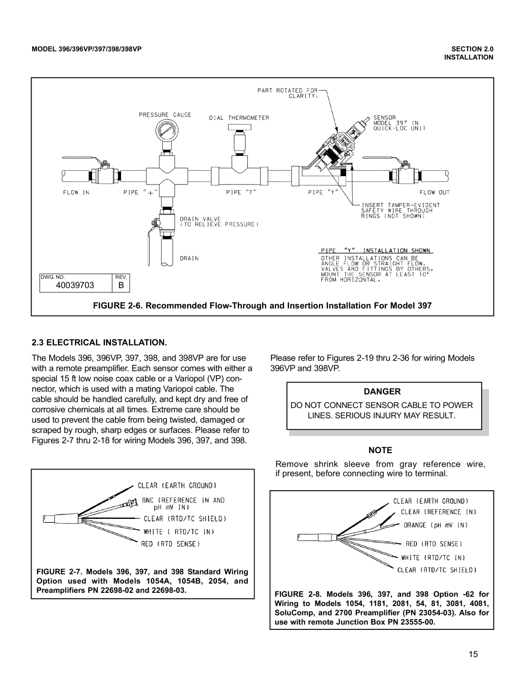
The Emerson 397 model focuses on flow measurement and control. It integrates technologies that minimize the impact of environmental factors on measurement accuracy. Its intelligent algorithms provide compensation for temperature and pressure fluctuations, ensuring consistent performance in varying conditions. This model is also compatible with various fieldbus protocols, facilitating easy integration into existing systems.
Finally, the Emerson 398 model is known for its high-performance digital operation. It includes features such as remote monitoring and control capabilities, which allow operators to manage processes from any location. The 398 is specifically designed to meet the rigorous requirements of industries like oil and gas, chemical, and power generation.
In summary, the Emerson 396, 398VP, 396VP, 397, and 398 models are equipped with cutting-edge technologies and features tailored for industrial efficiency, reliability, and accuracy. Their user-friendly interfaces, advanced diagnostics, and compatibility with modern communication protocols make them invaluable tools for engineers and operators in various sectors, enhancing overall productivity and performance.

