MODEL 400 and 400VP | WIRING |
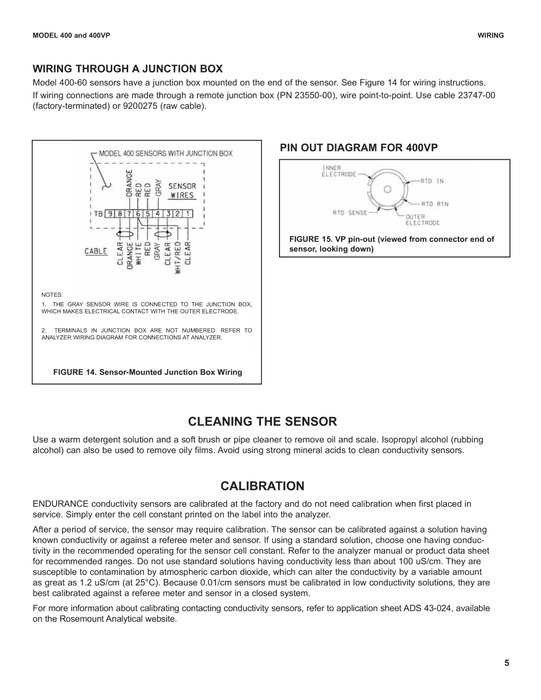
WIRING THROUGH A JUNCTION BOX
Model
If wiring connections are made through a remote junction box (PN
NOTES:
1.THE GRAY SENSOR WIRE IS CONNECTED TO THE JUNCTION BOX, WHICH MAKES ELECTRICAL CONTACT WITH THE OUTER ELECTRODE.
2.TERMINALS IN JUNCTION BOX ARE NOT NUMBERED. REFER TO ANALYZER WIRING DIAGRAM FOR CONNECTIONS AT ANALYZER.
FIGURE 14. Sensor-Mounted Junction Box Wiring
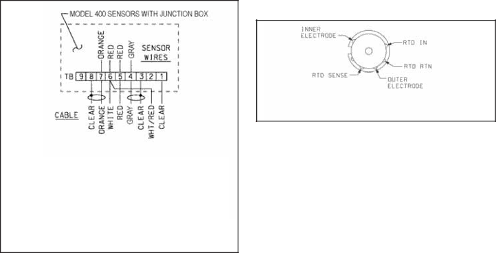
PIN OUT DIAGRAM FOR 400VP
FIGURE 15. VP pin-out (viewed from connector end of sensor, looking down)
CLEANING THE SENSOR
Use a warm detergent solution and a soft brush or pipe cleaner to remove oil and scale. Isopropyl alcohol (rubbing alcohol) can also be used to remove oily films. Avoid using strong mineral acids to clean conductivity sensors.
CALIBRATION
ENDURANCE conductivity sensors are calibrated at the factory and do not need calibration when first placed in service. Simply enter the cell constant printed on the label into the analyzer.
After a period of service, the sensor may require calibration. The sensor can be calibrated against a solution having known conductivity or against a referee meter and sensor. If using a standard solution, choose one having conduc- tivity in the recommended operating for the sensor cell constant. Refer to the analyzer manual or product data sheet for recommended ranges. Do not use standard solutions having conductivity less than about 100 uS/cm. They are susceptible to contamination by atmospheric carbon dioxide, which can alter the conductivity by a variable amount as great as 1.2 uS/cm (at 25°C). Because 0.01/cm sensors must be calibrated in low conductivity solutions, they are best calibrated against a referee meter and sensor in a closed system.
For more information about calibrating contacting conductivity sensors, refer to application sheet ADS
5