Multiple Reduction Plug Locations and Assignments
Frames 36 thru 38
All Foot, Flange, and Face Mounted Units
Mounting | Plug | Frame 36 | Frame 37 | Frame 38 | ||||
|
|
|
|
|
| |||
Position | Function | Input | Input | Input | ||||
|
| Shaft | Gearmotor | Shaft | Gearmotor | Shaft | Gearmotor | |
B3 and | Breather | 2 | 2 | 2 | 2 | 2 | 2 | |
Level ** | 2 | 2 | 2 | 2 | 2 | 2 | ||
B5 | Drain | 4 | 4 | 7 | 7 | 4 | 4 | |
| Filling | 2 | 2 | 2 | 2 | 1 | 1 | |
| Breather | 6 | 6 | 6 | 6 | 12 | 12 | |
B6 | Level ** | 6 | 6 | 6 | 6 | 12 | 12 | |
Drain | 10 | 10 | 10 | 10 | 4 | 4 | ||
| ||||||||
| Filling | 6 | 6 | 6 | 6 | 7 | 7 | |
| Breather | 10 | 10 | 10 | 10 | 11 | 11 | |
B7 | Level ** | 10 | 10 | 10 | 10 | 11 | 11 | |
Drain | 6 | 6 | 6 | 6 | 7 | 7 | ||
| ||||||||
| Filling | 10 | 10 | 10 | 10 | 4 | 4 | |
| Breather | 9 | 9 | 9 | 9 | 9 | 9 | |
B8 | Level | 3*** | 3*** | **** | **** | **** | **** | |
Drain | 2 | 2 | 2 | 2 | 2 | 2 | ||
| ||||||||
| Filling | 4 | 4 | 6 | 6 | 9 | 9 | |
V5 and | Breather | 5 | 5 | 5 | 5 | 13 | 13 | |
Level ** | 5 | 5 | 5 | 5 | 13 | 13 | ||
V1 | Drain | 3 | 3 | 3 | 3 | 14 | 14 | |
| Filling | 5 | 5 | 5 | 5 | 13 | 13 | |
V6 and | Breather | 3** | 3** | 3** | 3** | 14 | 14 | |
Level | 6* | 6* | 3 | 3 | 14 | 14 | ||
V3 | Drain | 5 | 8 | 5 | 8 | 13 | 13 | |
| Filling | 3 | 3 | 3 | 3 | 14 | 14 | |
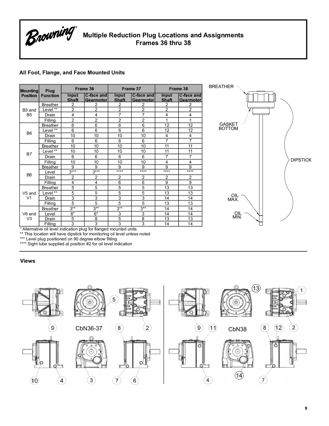
* Alternative oil level indication plug for flanged mounted units
**This location will have dipstick for monitoring oil level unless noted
***Level plug positioned on 90 degree elbow fitting
****Sight tube supplied at position #2 for oil level indication
BREATHER![]()
GASKET |
BOTTOM |
DIPSTICK
OIL
MAX.
OIL
MIN.
Views
13
CbN38
14
9