INSTALLATION (continued)
handle
shafts
handle
| handle |
|
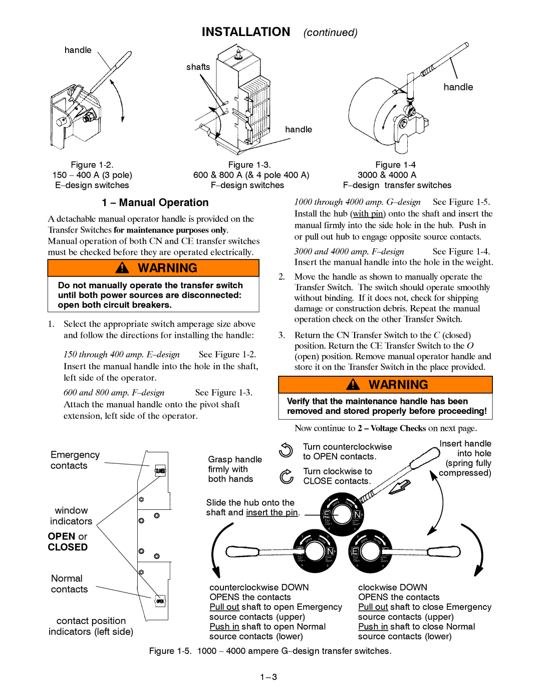
Figure | Figure | Figure |
150 – 400 A (3 pole) | 600 & 800 A (& 4 pole 400 A) | 3000 & 4000 A |
1 – Manual Operation
A detachable manual operator handle is provided on the Transfer Switches for maintenance purposes only. Manual operation of both CN and CE transfer switches must be checked before they are operated electrically.
Do not manually operate the transfer switch until both power sources are disconnected: open both circuit breakers.
1.Select the appropriate switch amperage size above and follow the directions for installing the handle:
150 through 400 amp.
600 and 800 amp.
Attach the manual handle onto the pivot shaft extension, left side of the operator.
1000 through 4000 amp. G–design See Figure 1-5.
Install the hub (with pin) onto the shaft and insert the manual firmly into the side hole in the hub. Push in or pull out hub to engage opposite source contacts.
3000 and 4000 amp. F–design See Figure 1-4.
Insert the manual handle into the hole in the weight.
2.Move the handle as shown to manually operate the Transfer Switch. The switch should operate smoothly without binding. If it does not, check for shipping damage or construction debris. Repeat the manual operation check on the other Transfer Switch.
3.Return the CN Transfer Switch to the C (closed) position. Return the CE Transfer Switch to the O (open) position. Remove manual operator handle and store it on the Transfer Switch in the place provided.
Verify that the maintenance handle has been removed and stored properly before proceeding!
Now continue to 2 – Voltage Checks on next page.
Emergency contacts
window
indicators
OPEN or
CLOSED
Grasp handle firmly with both hands
Slide the hub onto the shaft and insert the pin.
Turn counterclockwise | Insert handle | |
into hole | ||
to OPEN contacts. | ||
(spring fully | ||
Turn clockwise to | ||
compressed) | ||
CLOSE contacts. |
|
Normal contacts
contact position
indicators (left side)
counterclockwise DOWN | clockwise DOWN |
OPENS the contacts | OPENS the contacts |
Pull out shaft to open Emergency | Pull out shaft to close Emergency |
source contacts (upper) | source contacts (upper) |
Push in shaft to open Normal | Push in shaft to close Normal |
source contacts (lower) | source contacts (lower) |